
Project: HiCAD Plant Engineering
Plant Engineering > Isometry / Pipe Spool Drawing > Isometry settings
Plant Engineering > Isometry / Pipe Spool Drawing > Pipe spool drawing settings 
Isometry + Pipe spool drawing > Settings 
 The following description refers to isometries and pipe spool drawings.
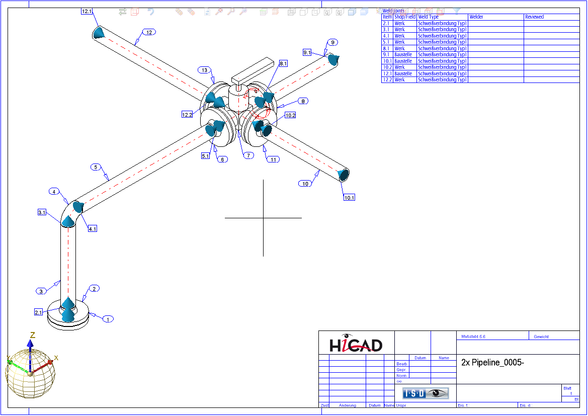
The Connections tab contains settings for the automatic generation of welded connection data on the component parts of a pipeline.
Connection type
Select the required type of connection. HiCAD supports the following types:
Assign item numbers
When assigning connection item numbers it is normally desired to exclude certain connection types from itemisation. This can be achieved by activation of this checkbox. To assign item numbers to a connection type, select the connection type from the list box, and activate the Assign item numbers checkbox.
This setting option is available for pipe spool drawings and isometries.
Use "Part.Connection" format
The itemisation of pipeline connections can assign item number, which use the item number of a part as a prefix and only count up the item of the connection in second place. To do so the checkbox must be activated.
Please note that the setting have to be modified for each connection type. You can e.g. itemise welded connections in this way and socket-welded connections in the previous way.
The part which provides the prefix is always the one directly before the connection in flow direction.
An example with displayed flow direction and parts itemised along the flow direction (identical part search: off):
Symbol for connection type
You can specify up to four symbols indicating diverse combinations, i.e:
Data record and place of construction
HiCAD differentiates between specifications for connection within a pipeline and connections on pipeline ends.
The type of welded connection is specified in the database, and its data managed in the same way as part master data. Select Info to display the attributes of the currently set connection type. Invoke the Select New option to select a different type, and specify the place where the connection was created.
Designations and symbols for place of construction
You can specify the designation used for text output to the graphic for the assembly location, e.g. Factory or Site. You can also select the symbol that should be set for the welded connection with the places of construction"factory" and "site".
Symbol number "0" means "no symbol".
If you select Default, pre-defined default values are assigned to the tab.
Symbolic representation of connection categories
Symbolic representations of connection categories for an isometric drawing can be made up of several elements:
Example: (1) Connection type: Socket-welded, (2) Place of construction: Site
Files containing symbolic representations are available for part variants (part symbols).
Example: (1) Connection type: Socket-welded, (2) Part symbol, (3) Place of construction: Site
Example: (1) Connection type: Socket-welded, (2) Plugged socket (Part symbol), (3) Place of construction: Site.
 Important:
The settings of this tab apply both to the pipe spool drawing and to the isometry and are saved in a parameter set together with the isometry settings to the file Anl3DIso.xml. This means that if the connection settings on the tab are changed with the Settings for isometry/pipe spool drawing function, the connection settings for the Pipe spool drawing settings function will also be changed automatically, and vice versa.


Settings (PE/Iso) • Isometry and Pipe Spool Drawing (PE/Iso) • Isometry and Pipe Spool Drawing Functions for the Layout Plan (PE)
|
© Copyright 1994-2019, ISD Software und Systeme GmbH |
