Project: HiCAD 3-D
Example: Cast Part
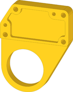
This example illustrates the conversion of the 2-D drawing shown below to the 3-D model of a cast part.
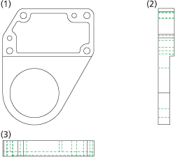
(1) front view, (2) side view, (3) top view
Proceed as follows:
Load the REKO_BSP4.SZN file and activate the conversion module (3-D Standard > New > Extruded  > 2-D->3-D Conversion). The derivation of the 3-D model comprises three steps:
Step 1: Define views
- Select the Views function from the 2-D->3-D Conversion menu.
- Create a selection box (1), (2) for the front view and specify the intersection point of the left edge and the upper edge as the reference point (3).
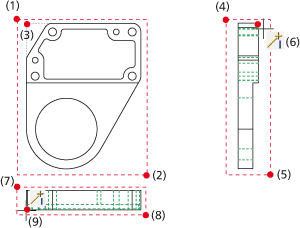
- Create a selection box (4), (5) for the side view and specify the end point of the right edge as reference point (6).
- Create a selection box (7), (8) for the top view and specify the start point of the upper edge as reference point (9).
Now select the required polylines.

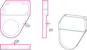
Step 2: Select polylines
- Select the Parts from View function from the 2-D->3-D Conversion menu.
- Identify
the polyline (1) in the front view.
- Identify the polyline (2) in the side view.
- Identify the polyline (3) in the top view.

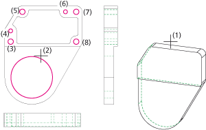
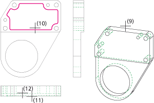
Step 3: Take over holes and subtractions
- Select the Holes function from the 2-D->3-D Conversion menu.
- Identify the 3-D model (1), then select the hole contours (2) - (8) in the front view.
- Right-click to end the hole contour selection. The holes will be created.
- Select the Subtractions function from the 2-D->3-D Conversion menu.
- Identify the
3-D model (9), then select the contour of the subtraction (10) in the front view.
- Right-click to end the selection.
- Identify the start edge (11) and the end edge (12) for the subtraction.


Example: Flange
• Example: Bracket
|
© Copyright 1994-2019, ISD Software und Systeme GmbH
Version 2402 - HiCAD 3-D
Date: 06/10/2019
|
> Feedback on this topic
|


 > 2-D->3-D Conversion). The derivation of the 3-D model comprises three steps:


