You use the functions of the Notch menu to connect one beam to another by cutting areas of the beam to fit ("notching"). The beam to be connected is assigned a notch in the process. This can be done with or without lengthening the beam to be connected. You can use the existing notch parameters or set new ones.
|
Notch with lengthening, current parameters The notch is made with lengthening, using the current notch parameters. Select Steel Engineering > Management > Settings, Steel Engineering to define these parameters. First, identify the beam to be notched and then the beam to which you want to make the connection. HiCAD automatically assigns a notch to the beam that is identified first. |
|
|
Notch without lengthening, current parameters As above, but without lengthening. |
If you do not want to use the current parameters, click to open a pull-down menu with the following functions:
|
Notch, New parameters, With lengthening The notch is made with lengthening. First, the Notch Parameters tab of the Steel Engineering > Management > Settings, Steel Engineering function is displayed. Here, you change the notch type, the length and height of the notch etc. If you choose OK to exit the window, the new settings are applied. These parameters are used for notches that are generated subsequently - during the current HiCAD session. |
|
|
Notch, New parameters, Without lengthening As above, but without lengthening. |
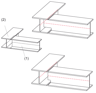
Left: (1) Beam to be connected, (2) Beam to
which the connection is made
Top right: Notch with lengthening, Bottom right: Notch without lengthening
Left: Beam to be connected (1) and beam to which the connection is made, Centre: Notch of type Radius, Right: Notch of type bore
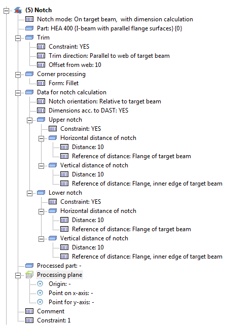
The feature log for Notches in Steel Engineering is now much more detailed. This allows an extensive processing and modifying of notches directly via the feature log. Examples of this are:
The content of the feature log depends on the parameter settings at the moment of notch creation.
The target beam for the connection must have at least one flange that allows the calculation of the outer contour. Such beams are: I-, L-, U-, T- or Z-beams. Not only standard beams, but also prototype beams of this type are allowed.
Process Beams (3-D SE) • Steel Engineering Functions
© Copyright 1994-2018, ISD Software und Systeme GmbH |