Besides the stiles, rungs, landings, cage rings, transitions and connections, you can also use your own 3-D parts or assemblies for the configuration of vertical ladders. These must be available as KRA files and fulfil certain conditions to be placed correctly into the ladder construction.
The conditions:
|
Meaning |
Name |
Feature variable |
|||||
|---|---|---|---|---|---|---|---|
|
Point 1 |
Origin of coordinate system |
#1 |
x |
part_n1_insertion_xa |
|||
|
|
|
|
y |
part_n1_insertion_ya |
|||
|
|
|
|
z |
part_n1_insertion_za |
|||
|
Point 2 |
Point on X-axis |
#2 |
x |
part_n1_insertion_x1 |
|||
|
|
|
|
y |
part_n1_insertion_y1 |
|||
|
|
|
|
z |
part_n1_insertion_z1 |
|||
|
Point 3 |
Point on Y-axis |
#3 |
x |
part_n1_insertion_x2 |
|||
|
|
|
|
y |
part_n1_insertion_y2 |
|||
|
|
|
|
z |
part_n1_insertion_z2 |
|||
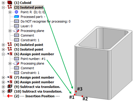
The image below shows the supplied file HOLM_2.KRA with feature log and isolated points.

 Please note:
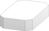
Let us assume that you want to use a part as shown below as a stile for your ladder configuration:

Step 1: Create cuboid
First create a cuboid ( Length 30, Width 50, Height 10) with the name stile_exp. Make sure that the Feature  checkbox is activated.
Step 2: Assign variables
Now the cuboid needs to be parameterised. The stile can then be used for the configuration of ladders of different heights. Assign different variables names to the length, width and height of the cuboid. As the length of the cuboid corresponds to the width of the stile to be created (stile_width in the configuration of the ladder), enterwidth as the neme of the variable. The start value remains unchanged. Proceed likewise with the Width (length) and Height (height) of the cuboid. To assign the variables, double-click the corresponding entry in the feature log, enter the name of the variable and confirm the start value.
Step 3: Specify isolated points
To insert the isolated points, open the 3-D-Standard tab and select Tools > New point .For point specification, use the point option Relative in conjunction with a reference point identification. Press R on your keyboard, left-click, identify the reference point and enter the required coordinates. In our example, the Autopilot is used for reference point identification.
Please make sure that the representationn of isolated points has been activated! If required, open the Drawing tab and select Others > Visualisation > Hide/Show, Via element type, and then activate the visualisation of isolated points.
Specify the 3 points as follows:
| Point | Reference point | Coordinates | |
|---|---|---|---|
|
Point 1 |
Bottom left corner of cuboid (Point option I) |
x=0, y=0, z=0 |
|
|
Point 2 |
Point 1 (Point option J via Autopilot) |
x=5, y=0, z=0 |
|
|
Point 3 |
Point 1 (Point option J via Autopilot) |
x=0, y=5, z=0 |
|
Schritt 4: Parameterise coordinates
Now you need to assign the required variables names to the isolated points: Double-click the corresponding entry in the feature log, enter the name of the variable and confirm the start value.
|
Point |
Feature variable |
Start value |
||
|---|---|---|---|---|
|
Point R (0,0,0) |
x |
part_n1_insertion_xa |
0 |
|
|
|
y |
part_n1_insertion_ya |
0 |
|
|
|
z |
part_n1_insertion_za |
0 |
|
|
Point R (5,0,0) |
x |
part_n1_insertion_x1 |
5 |
|
|
|
y |
part_n1_insertion_y1 |
0 |
|
|
|
z |
part_n1_insertion_z1 |
0 |
|
|
Point R (0,5,0) |
x |
part_n1_insertion_x2 |
0 |
|
|
|
y |
part_n1_insertion_y2 |
5 |
|
|
|
z |
part_n1_insertion_z2 |
0 |
|
Step 5: Assign point numbers
To assign a point number (i.e. a designation) to an isolated point, use the New point number function. To access this function, open the 3-D Standard tab and select Tools > New points  > New point number
  . Identify the previously specified isolated points one after the other and initially enter the names P1, P2 and P3 aspoint designations. For each point designation a corresponding feature item will be entered into the feature log.
In the feature log, double-click the Point number... sub-item of the Assign point number entries, and change the names to #1, #2 and #3. Please pay attention to the correct assignment of names: #1 = Point R (0,0,0), #2 = Point R (5,0,0), #3 = Point R (0,5,0).
Step 6: Place isolated points on Layer 0 (invisible)
Now assign the isolated points to the invisible Layer 0. In the feature log, double-click the Layer... sub-item of the corresponding Isolated point entry and enter the value 0.
Step 7: Chamfer cuboid
Finally, apply chamfers to the edges of the cuboid. Open the 3-D Standard tab and select the Chamfer  function. Enter 5 as chamfer length and identify the four external, vertical edges.
Step 8: Save stile
Right-click the part name in the ICN and activate the Reference part, Save, Detail drawing  function. Select the options Withot referencing, Save as part and Without database. Save the 3-D part with the name STILE_EXP to the directory HICAD > KATALOGE > WERKSNORMEN > STAHLBAU > PRODUKTE > STEIGLEITER.
Step 9: Fit vertical ladder with new stile
The stile created in the previous steps can now be used for the configuration of a vertical ladder:
Activate the Vertical ladder function and select the entry KraPArtHolm in the Stile type field. Click the  icon and select the KRA file you created in our example. Click OK to start the fitting process of the ladder.

Configure and Fit Vertical Ladder (3-D SE) • Vertical Ladder (3-D SE) • Create Configuration of Vertical Ladder (3-D SE) • Stairs and Railings (3-D SE)
|
© Copyright 1994-2018, ISD Software und Systeme GmbH |