Gratings (3-D SE)
Steel Engineering > Plate, new > Others > Grating DIN 24537, from sketch 
You use this function to derive grating steps as per DIN 24537 from
a sketch that exists in the drawing
- First, choose
the desired implementation:
- P
Pressed grating (cross-bars made of flat steel)
- SP
Welded pressed grating (cross-bars made of four-bar steel)
- Choose from the
list of suitable dimensions:
- Bearing bar height
(for P)
- Nominal mesh width
(for WP)
- Then identify
the sketch.
- Specify the bearing bar orientation by identifying a straight edge or specifying two points. This enables the determination of the rotation angle in relation to the x-axis of the generative sketch.
- HiCAD displays a preview of the grating step. Specify a fitting
point on the grating step and the position of this point in the drawing.
- You can then fit more steps of the selected type
or use the middle mouse button (ESC) to end the function.

 Please note:
- To insert the grating as a sub-part, click
 and select the corresponding function.
- If the grating is fitted as a sub-part,the active part will be used as the reference part. If the active part is an assembly part, the grating will directly be fitted as a sub-part of this assembly part. If the active part is the main part of an assembly, the new grating is created as a sub-part to the assembly part belonging to the main part. In case of a BOM-relevant active part that is neither an assembly part nor a main part of an assembly, a new assembly will be formed. The active part of this assembly will then become the main part, and the grating the sub-part of this new assembly.
- You can change the gearing bar orientation subsequently. This can be done via the Feature log, or by entering a different rotation angle, or with the Grating step, Change bearing bar orientation function.
- You can also use the Grating from sketch (3-D SE) function in the context menu of the sketch for the creation of gratings. Please note that if the sketch belongs to an assembly, the grating will also be assigned to this assembly.
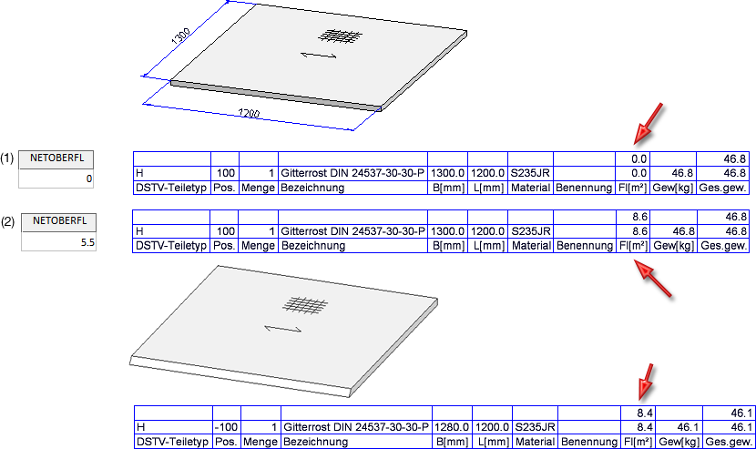
- For Gratings acc. to DIN 24537 you can specify the surface area per square metre of installation area. For this purpose, the NETOBERFL column in the corresponding table of the catalogue Editor is available.

The default setting is 0. To calculate the net weight and the net surface area, enter the desired value and save the table.
When the gratings are inserted, the value specified in the table will be considered for the net weight calculation. Furthermore, subtractions and chamfers will also be considered for weight calculation.

(1) Grating insertion with value 0; (2) Grating insertion with value 5.5, (3) Grating with chamfer


Plates (3-D
SE) • Steel Engineering Functions
|
© Copyright 1994-2018, ISD Software und Systeme GmbH
Version 2302 - HiCAD Steel Engineering
Date: 28/09/2018
|
> Feedback on this topic
|


 Please note:
  and select the corresponding function.

