When you itemise the drawing, the Powder marking lines and punch marks acc. to DSTV-NC export checkbox shold be active, to ensure that the corresponding data will be considered for DSTV-NC export.
 This function enables you to prepare HiCAD files for export to NC equipment. The type of machine targeted determines whether the DSTV-NC or NCX Interface will be selected.
The NC Interface creates for each itemised part a NC file with the file name extension .NC. This file contains information such as attributes of the part, processings (maximum bore diameter, arcs etc.). The designation drawing_Pn is used as file name, with drawing being the name of the current drawing and n the item number of the corresponding part.
When you itemise the drawing, the Powder marking lines and punch marks acc. to DSTV-NC export checkbox shold be active, to ensure that the corresponding data will be considered for DSTV-NC export.
 Please remember that only itemised parts can be exported!
To export a file via the DSTV NC interface, select  >
>  Save as > Further... >
  DSTV-NC.
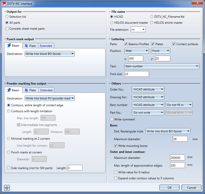
The dialogue window consists of the following areas:
Please also read the information given in the paragraphs Templates for attribute assignment and the notes at the bottom of this page.
Please note:
The settings for DSTV export can be saved as Favourites and re-used at any time. To do this, click the  icon at the bottom left of the window. The Favourites for DSTV-NC export will be saved as XML files to the directory Configuration\Favourites\SteelEngineering\DSTV-NC of your HiCAD installation.
Favourites are saved to the same-named sub-folder of the directory in which the HiCAD Configuration database is also located. If you have installed HiCAD from the red DVD with the ISD default settings, this will be the folder ProgramData\ISD Software und Systeme\HiCAD nnnn, with nnnn being the HiCAD version, e.g. 2017.
More on Favourites Management can be found in the Manage Favourites topic of HiCAD Basics Help.

At the top left of the window you can choose beneath Output for whether you want to apply the export to a Selection list (= the active part list) or to All parts.
If you want Sheet Metal part developments to be included in the DSTV-NC export, activate the Consider sheet metal parts checkbox.
At the top right of the window you can choose beneath File name whether it is to be generated according to the HiCAD file name, the HELiOS document master or the HELiOS article master (if you are working with a HELiOS database). Choose the option DSTV_NC_Filename.ftd if you want the file name to be exported according to this template file and the corresponding annotation of your HiCAD drawing.
If there are any Punch marks, you can determine whether you want to apply them to the part and if so, specify their position via the corresponding tab for beams or plates:
If you click the Extended button and activate the Calculate punch marks automatically checkbox, missing punch marks will be automatically calculated and written into the DSTV-NC file. Already existing punch marks will not be replaced or changed.
If you also activated the Display punch marks as points checkbox, the automatically calculated punch marks will not only be exported to the file, but also made visible in the HiCAD drawing. They will be displayed as isolated points, and not as "real" processings. The exact edge distance can be specified in the input field below the checkboxes.
You proceed likewise for Powder marking line output:
In the Beam and Plate tab you can specify various settings, such as the general Length of the Side marking, or extended settings concerning contours and identifications.
Besides the representation option Contours, entire length of contact edge option, you can choose between the following three other options:
Contours with length limitation: For the representation of the mounting of longer parts, the powder marking line can be replaced with a intermediate segmented line whose segment lengths and the distances between them can be specified. Default values are a length of 15 mm and a distance of 500 mm.
Minimal markings at 2 corners: Marks two corners and the connecting side of the attachment part. Specify a value for the Line length for corners.
Punch marks at corners: For symmetrical parts that are rotated 90 or 180 degrees about the beam axis, there will be several possible attachment positions. This requires a clear an unambiguous marking of the connection side by means of punch marks. Specify a Diameter.
1: Contour representation, entire length; 2 Contour representation, limited length
In the Extended tab you to specify parameters for Tolerance for powder marking line search, such as Distance tolerance, Angle tolerance and Minimum length.
In the Powder marking line output area, activate the Manually created option if you want manually created powder marking lines to be output. The corresponding input fields on the Beam and Plate tabs will then be greyed out. If you activate the Automatic option, powder marking lines will be created automatically. Manually created lines will not be considered.
 > Change font). If you change the part attribute for the file DSTV_NC_Signaturtext.ftd there, it will be written to the position for the lettering in the DSTV-NC file.
For Order No., Drawing No., Item number and Part No. you have the following setting options in a pull-down menu:
Beside Item number and Part No. you can additionally specify the number of decimal places for the written out result, if you have selected HiCAD attribute.
Please note:
> Change - Settings). If you change the attribute for the corresponding file there (and save the file), it will be written to the relevant place in the DSTV-NC file. The advantage of this is that various information can be written into both places in the DSTV-NC file. Furthermore, you can specify a Maximum diameter for bores beneath Bore.
By deactivating the Write mounting bores checkbox you can exclude bores from the export.
You can enter a Maximum diameter for the arcs of the Outer and inner contours, and specify whether slots or rectangular holes are to be written into the block BO (bore) or IK (inner contour). If you want to output an additional value for the third coordinate or the radius (even if the radius is 0), activate the Value for 0-radius checkbox.
After having specified all required settings, confirm with OK and, in the following dialogue, specify a path for the export files. The file extension can be freely selected, e.g. if a saving in the "nc1" format is required.
Open the Drawing tab and choose Itemisation/Detailing > Attr. > Templates, Attribute assignment  to open the Templates, Attribute assignment dialogue window.
Scroll down to the DSTV-NC section.
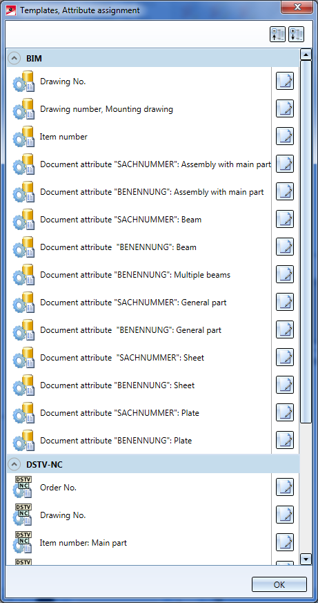
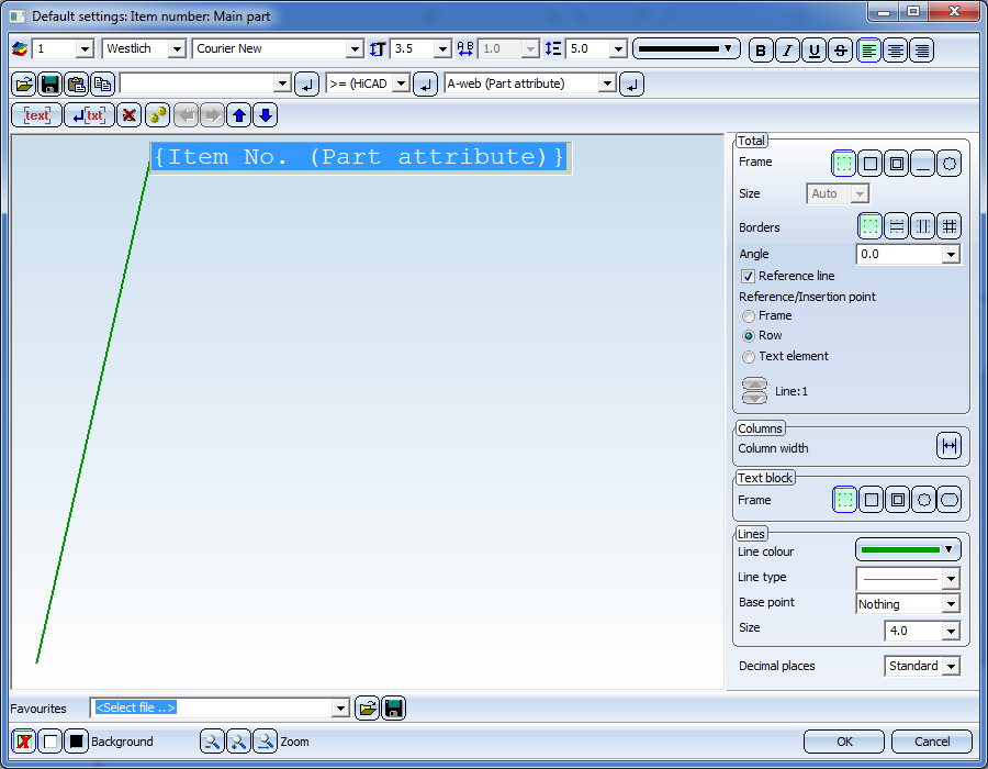
Clicking one of the editing symbols opens the Editor for for the annotation settings - here, the Item number: Main part entry has been chosen:
The templates for attribute assignment for DSTV-NC export are FTD files, too; they are located in the sys directory of your HiCAD installation. Supplied with HiCAD are the templates listed below:
|
Templates file |
Settings for |
Pre-setting |
|
DSTV_NC_Ordernumbertext .FTD |
Order number |
%TS(TEXTE760) %TS(TEXTE760) stands for the content of the text key TEXTE760, which is the text Order number: |
|
DSTV_NC_Drawingnumbertext .FTd |
Drawing number |
%TS(TEXTE1AN113) %TS(TEXTE1AN113) stands for the content of the text key TEXTE1AN113 which is the text Drawing number: |
|
DSTV_NC_H_Itemnumbertext .FTd |
Item number for main parts |
{Item number (Part attribute)} |
|
DSTV_NC_H_Partnumbertext .FTd |
Part number for main parts |
not allocated |
|
DSTV_NC_Itemnumbertext .FTD |
Item number for loose parts |
{Item number (Part attribute)} |
|
DSTV_NC_Partnumbertext .FTD |
Part number for loose parts |
not allocated |
|
DSTV_NC_W_Itemnumbertext .FTD |
Item number for attached parts |
{Item number (Part attribute)} |
|
DSTV_NC_W_Partnumbertext .FTD |
Part number for attached parts |
not allocated |
|
DSTV_NC_Signaturetext .FTD |
Signature |
{Item number (Part attribute)} |
|
DSTV_NC_Filename .FTD |
File name - NC |
{Item number (Part attribute)} |

DTSV Product Interface • DSTV BOM Interface • Steel Engineering Interfaces
|
© Copyright 1994-2018, ISD Software und Systeme GmbH |