 > Bore pattern
 3-D Standard > Standard Processings > Bore  > Bore pattern
 ![]()
HiCAD has a library of bore patterns (e.g. Agrafes), which you can insert into your Sheet Metal part. To expand the library you can use
The insertion into Sheet Metal parts takes place with the 3-D function Bore pattern. Proceed as follows:
If you want to punch several flanges of a Sheet Metal main part simultaneously, activate the Sheet Metal main part.
Once you have selected the function, the Setting dialogue window appears.
Select Exit surface for the punching of only one flange.
The selection window containing the punching tools opens. The selection is displayed as a tree structure, as is standard in Windows.
You can now insert the tool individually or compile a group via the Grid menu that appears.
The sheet will then be punched. You can now insert the punch once more. Alternatively, you can use the right mouse button to activate a context menu before defining the new fitting position. The functions of this context menu allow you, for example, to change the fitting direction if desired. Use the middle mouse button to end the function.

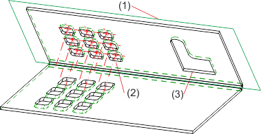
(1) Processing plane
(2) Complete Sheet Metal part, punched (through)
(3) Bore pattern "Agrafe" (to exit surface)
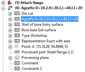
 Die Musterbohrung wird in das Featureprotokoll des Blechteils eingetragen und kann mit einem Doppelklick auf den Eintrag z.B. Agraffe geändert werden.


|
© Copyright 1994-2018, ISD Software und Systeme GmbH |