:D
Dimensioning rules can be divided into different groups:
In the Dimensioning Rule Editor the dimensioning rules can be filtered by these groups.
![]() Please also note the information in Notes on dimensioning rules section.
Please also note the information in Notes on dimensioning rules section.

|
Value |
Description |
Designation / Rule Identifier |
|---|---|---|
|
1 |
Length between system axes |
SYSTEMLENGTH |
|
71 |
Sub-system in upper flange area |
SUBSYSTEM_UPPERFLANGE Only grid and sub-grid lines, but no parts will be dimensioned! |
|
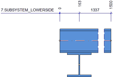
72 |
Sub-system in lower flange area |
SUBSYSTEM_LOWERFLANGE Only grid and sub-grid lines, but no parts will be dimensioned! |
|
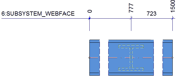
73 |
Sub-system in web area |
SUBSYSTEM_WEBFACE Only grid and sub-grid lines, but no parts will be dimensioned! |
|
74 |
Sub-system in upper flange and lower flange area |
SUBSYSTEM_FLANGES Only grid and sub-grid lines, but no parts will be dimensioned! |
|
75 |
Sub-system in upper flange, lower flange and web area |
SUBSYSTEM_WEB_AND_FLANGES Only grid and sub-grid lines, but no parts will be dimensioned! |
|
Value |
Description |
Designation / Rule Identifier |
|---|---|---|
|
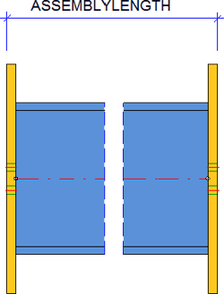
2 |
Assembly length |
ASSEMBLYLENGTH |
|
19 |
Assembly height |
ASSEMBLY_HEIGHT |
|
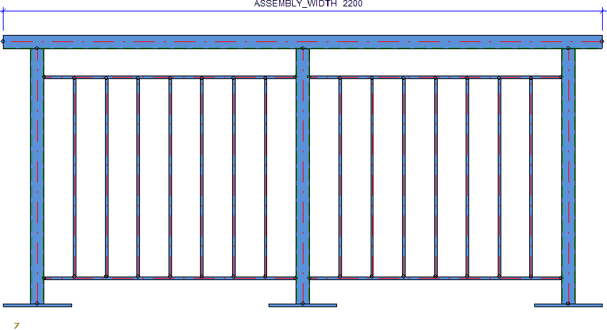
20 |
Assembly length |
ASSEMBLY_WIDTH
|
|
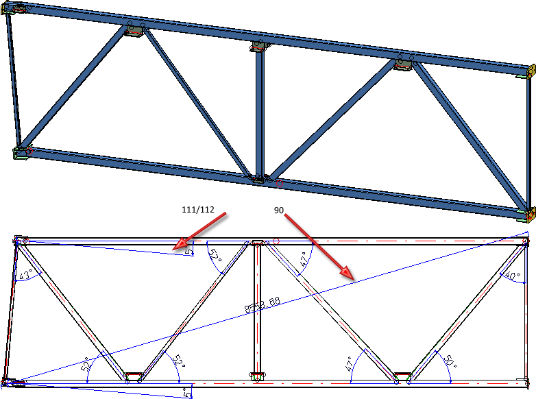
90 |
Diagonal total dimensions of an assembly |
TOTAL_SIZE_ASSEMBLY Especially for framework constructions (assembly without main part) |
|
Value |
Description |
Designation / Rule Identifier |
|---|---|---|
|
3 |
Axis length |
LENGTH_OF_AXIS |
|
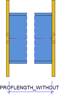
4 |
Beam length without front-mounted attached parts |
PROFLENGTH_WITHOUT |
|
9 |
Beam/profile length with front-mounted attached parts |
PROFLENGTH_WITH |
|
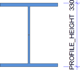
17 |
Beam height |
PROFILE_HEIGHT |
|
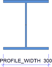
18 |
Beam width |
PROFILE_WIDTH
|
|
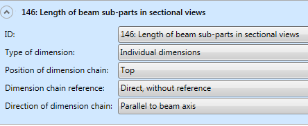
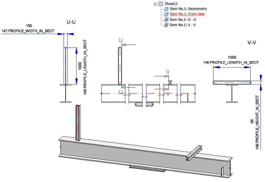
146 |
Length of beam sub-parts in sectional views |
PROFILE_LENGTH_IN_SECT
|
|
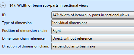
147 |
Width of beam sub-parts in sectional views |
PROFILE_WIDTH_IN_SECT
|
|
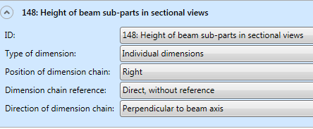
148 |
Height of beam sub-parts in sectional views |
PROFILE_HEIGHT_IN_SECT |
|
Value |
Description |
Designation / Rule Identifier |
|---|---|---|
|
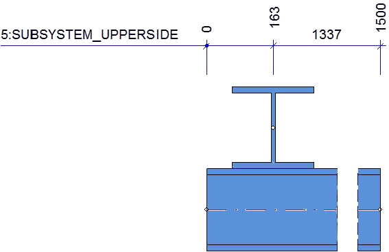
5 |
Sub-system, Upper beam side |
PROFSYSTEM_UPPERSIDE Only beams with cross-sections || to screen plane, || to beam axis
|
|
6 |
Sub-system, Web surface of beam |
PROFSYSTEM_WEBFACE
|
|
7 |
Sub-system, Lower beam side |
PROFSYSTEM_LOWERSIDE |
|
8* |
Attached parts (via outer contour) |
ATTACHING_PARTS via outer contour, not via bores |
|
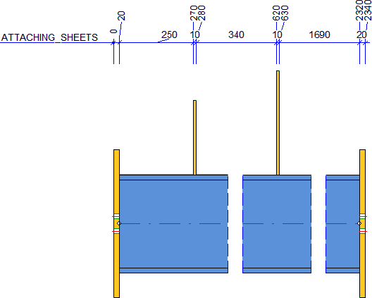
10* |
Attached sheets/plates with bores |
ATTACHING_SHEETS Attached sheets/plates via bore or outer contour |
|
26 |
Bores in front plates |
BORES_IN_FRONT_PLATE |
|
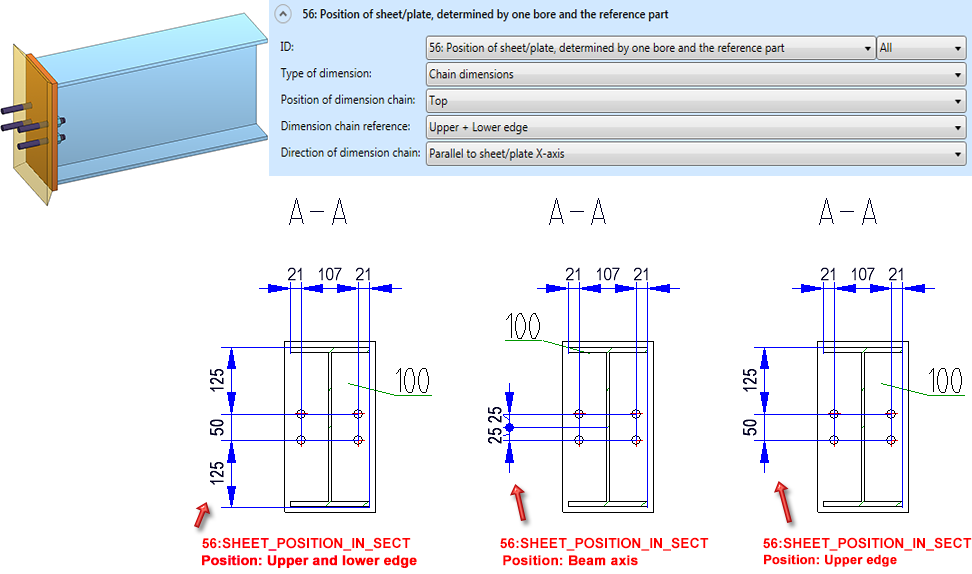
56 |
Position of sheet/plate, determined by one bore and the reference part |
SHEET_POSITION_IN_SECT
Top and bottom refer to the sheet's coordinate system rather than the beam. |
|
57 |
Attached plates, one chain of dimension for each plate |
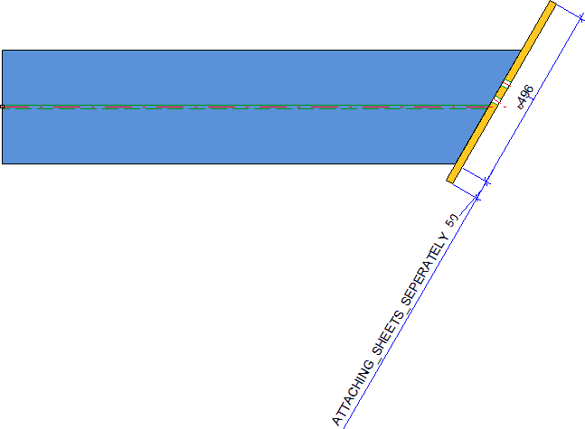
ATTACHING_SHEETS_SEPERATELY Via bores, if they are dimensioned perpendicular to screen plane and bores of sub-parts are dimensioned, or via outer contour; this is the only beam-related rule for which the direction VERTIKALSHEETAXIS is allowed in connection with the position INSIDE, in order to, e.g. dimension front plates on cuts in sheet/late direction! |
|
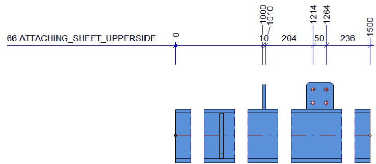
66* |
Attached plates on top side of beam, via bores or outer contour |
ATTACHING_SHEET_UPPERSIDE |
|
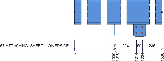
67* |
Attached plates on bottom side of beam, via bores or outer contour |
ATTACHING_SHEET_LOWERSIDE |
|
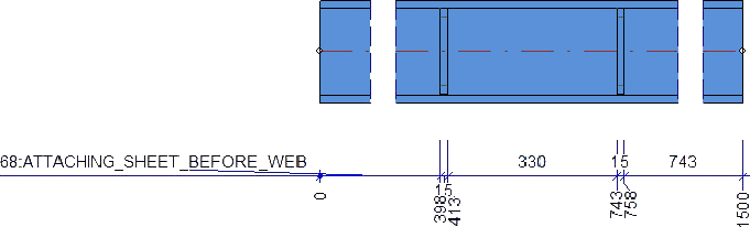
68* |
Attached plates on web surface, in front of web, via bores or outer contour |
ATTACHING_SHEET_BEFORE_WEB |
|
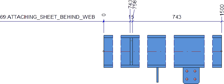
69* |
Attached plates on web surface, behind web, via bores or outer contour |
ATTACHING_SHEET_BEHIND_WEB |
|
70* |
Attached beams/profiles with axis, to main part axis, dimension via system axis |
ATTACHING_PROFILES_VERT
|
|
83 |
Attached plates with bores, incl. bore in side view |
ATTACHING_SHEETS_VERT |
|
84 |
Bores in sub-parts (bores of all sub-parts) incl. bores + viewing direction |
SUBPARTBORES_VERT |
|
89 |
All parts via bore |
ALL_PARTS_BORES |
|
111 |
Angle between beam main part and connected sub-part beams |
STWDimRuleIdent_ANGLE_CONNECTED_PROFILES |
|
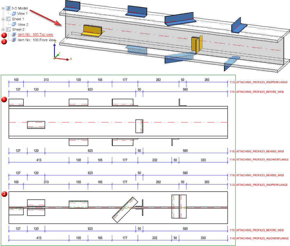
113* |
Beam sub-parts, not vertical to main part axis |
ATTACHING_PROFILES_INUPPERFLANGE |
|
114* |
Beam sub-parts on lower flange, not vertical to main part axis |
ATTACHING_PROFILES_INLOWERFLANGE |
|
115* |
Beam sub-parts in front of web, not vertical to main part axis |
ATTACHING_PROFILES_BEFORE_WEB |
|
116* |
Beam sub-parts behind web, not vertical to main part axis |
ATTACHING_PROFILES_BEHIND_WEB |
|
117* |
Beam sub-parts, not vertical to main part axis |
ATTACHING_PROFILES |
|
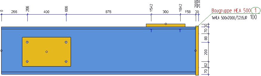
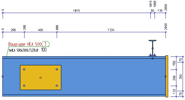
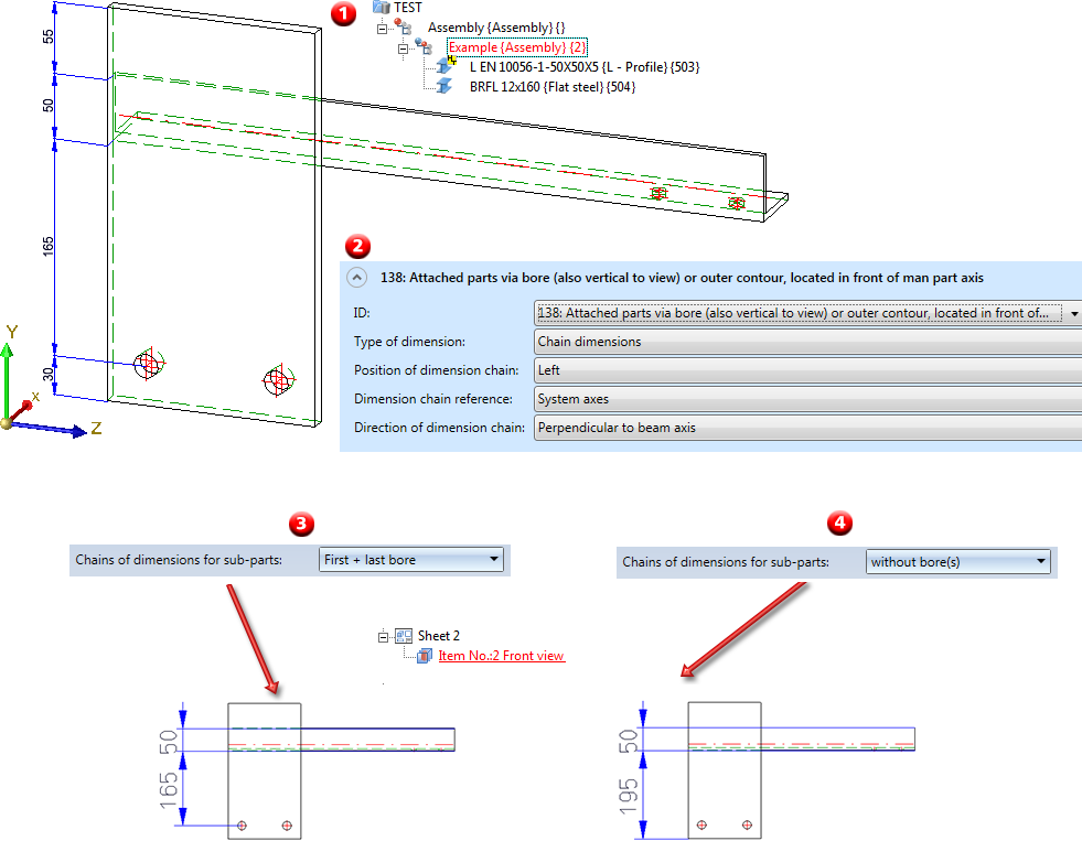
138 |
Attached parts via bores (also perpendicular to view) or outer contours, located before the axis of the main part |
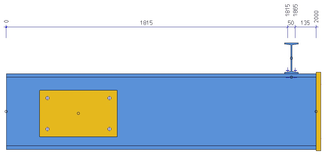
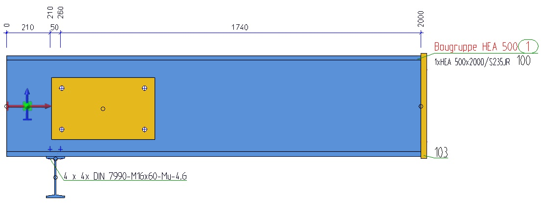
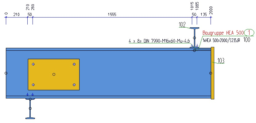
ATTACHING_PARTS_VERT_BEFORE_AXIS The image below shows a beam main part and a plate with 2 bores as attached part (1). In the configuration the Dimensioning rule 138 has been applied as shown below (2). (3) and (4) show the front view in the workshop drawing. In (3) the attached parts are dimensioned via bores, in (4) via the outer contour.
|
|
139 |
Attached parts via bores (also perpendicular to view) or outer contours, located behind the axis of the main part |
ATTACHING_PARTS_VERT_BEHIND_AXIS |
|
140 |
Attached parts via bores (also perpendicular to view) or outer contours, located above the axis of the main part |
ATTACHING_PARTS_VERT_ABOVE_AXIS |
|
141 |
Attached parts via bores (also perpendicular to view) or outer contours, located below the axis of the main part |
ATTACHING_PARTS_VERT_BELOW_AXIS |
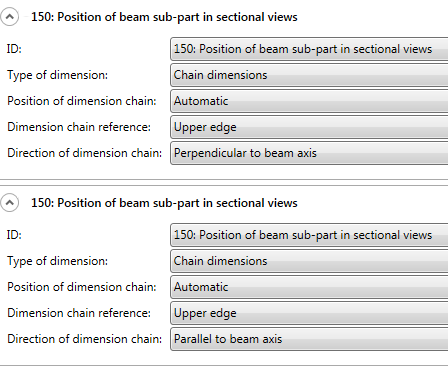
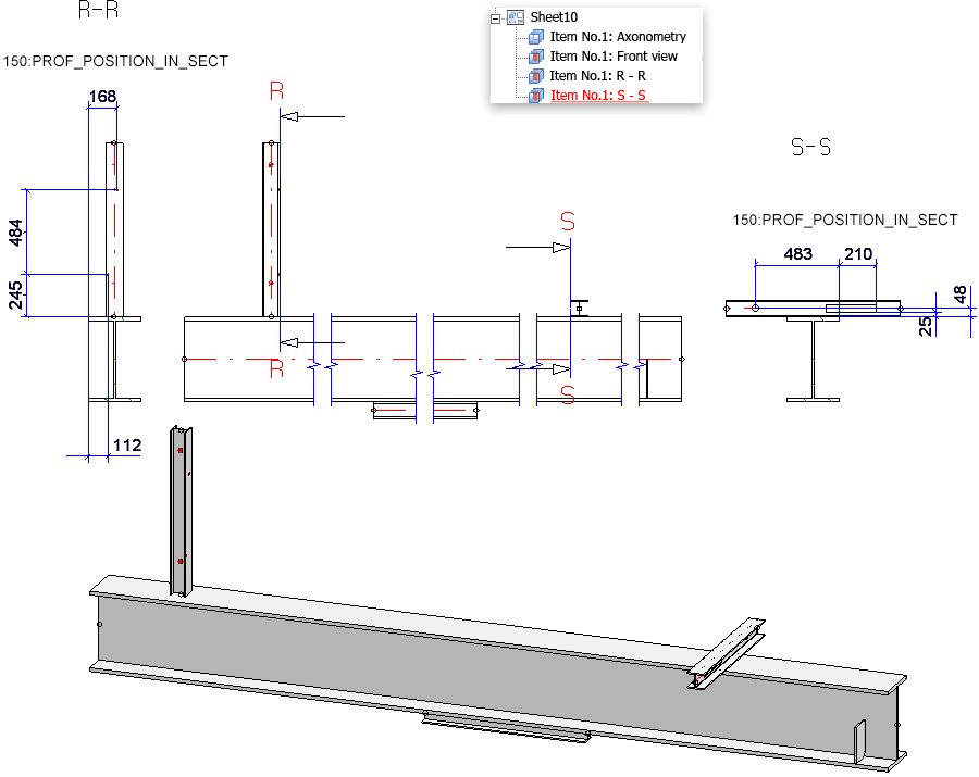
| 150 |
Position of beam sub-part in sectional views |
PROF_POSITION_IN_SECT |
*see Dimensioning Rules - Overview (3-D SE)
|
Value |
Description |
Designation / Rule Identifier |
|---|---|---|
|
11 |
Bores in sub-parts |
SUBPARTBORES |
|
12 |
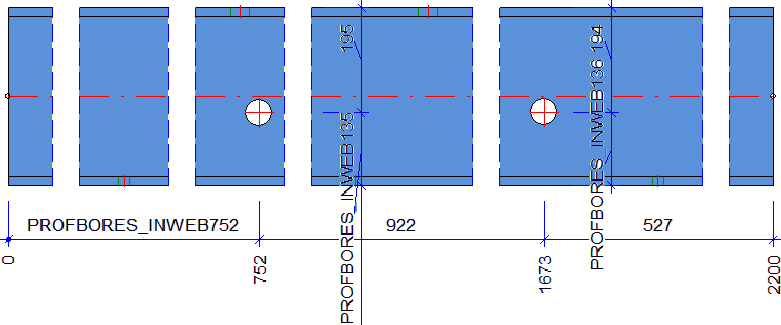
Bores in web of beam |
PROFBORES_INWEB |
|
13 |
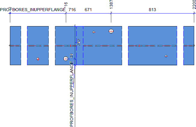
Bores in upper flange of beam |
PROFBORES_INUPPERFLANGE
|
|
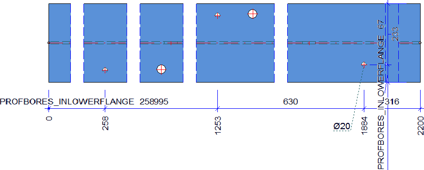
14 |
Bores in lower flange of beam |
PROFBORES_INLOWERFLANGE |
|
15 |
Bores in upper and lower flange of beam |
PROFBORES_INFLANGES |
|
16 |
16: Bores in beams - Offset parallel to beam axis |
PROFBORES_SYSTEMOFFSET_PARALLEL |
|
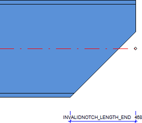
21 |
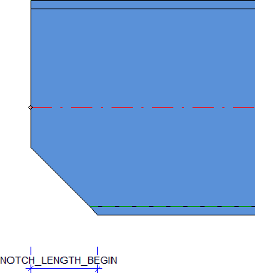
Notch length at start |
NOTCH_LENGTH_BEGIN |
|
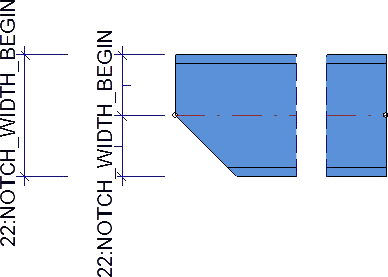
22 |
Notch length at start |
NOTCH_WIDTH_BEGIN |
|
23 |
Notch length at end |
NOTCH_LENGTH_END |
|
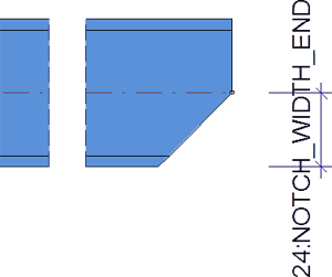
24 |
Notch width at end |
NOTCH_WIDTH_END |
|
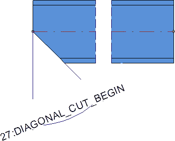
27 |
Oblique cut on beam at start |
DIAGONAL_CUT_BEGIN |
|
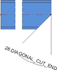
28 |
Oblique cut on beam at end |
DIAGONAL_CUT_END |
|
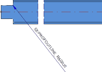
58 |
Fillet radii on beam notches |
PROFOUTLINE_RADIUS |
|
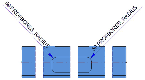
59 |
Fillet radii at material subtractions on beams/profiles |
PROFBORES_RADIUS |
|
64 |
Length of cut at beam/profile start |
SECTION_LENGTH_BEGIN |
|
65 |
Length of cut at beam/profile end |
SECTION_LENGTH_END |
|
85 |
Beam processing in web, incl. processings in side view |
PROFBORES_INWEB_VERT |
|
86 |
Beam processings in upper flange, incl. processings in side view |
PROFBORES_INUPPERFLANGE_VERT |
|
87 |
Beam processings in lower flange, incl. processings in side view |
PROFBORES_INLOWERFLANGE_VERT |
|
88 |
Beam processings in upper and lower flange, incl. processings in side view |
PROFBORES_INFLANGES_VERT |
|
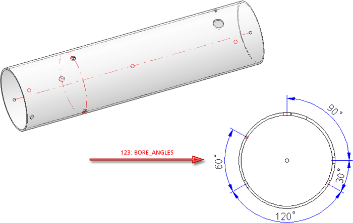
123 |
Angle between bore axes |
BORE_ANGLES (only in view from left and right and only parallel to screen plane!) |
|
124 |
Beam processings of the type Slot |
PROF_LONGHOLES_ONLY
|
|
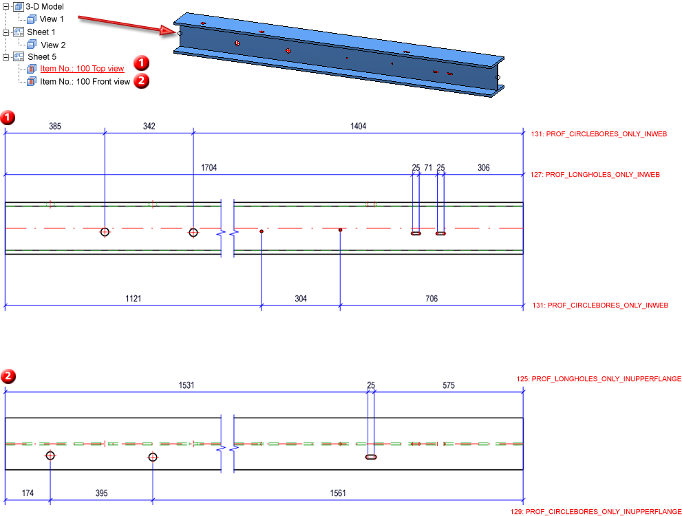
125 |
Beam processings of the type Slot in upper flange |
PROF_LONGHOLES_ONLY_INUPPERFLANGE |
|
126 |
Beam processings of the type Slot in lower flange |
PROF_LONGHOLES_ONLY_INLOWERFLANGE |
|
127 |
Beam processings of the type Slot in web |
PROF_LONGHOLES_ONLY_INWEB |
|
128 |
Beam processings of the type Circular bore |
PROF_CIRCLEBORES_ONLY |
|
129 |
Beam processings of the type Circular bore in upper flange |
PROF_CIRCLEBORES_ONLY_INUPPERFLANGE |
|
130 |
Beam processings of the type Circular bore in lower flange |
PROF_CIRCLEBORES_ONLY_INLOWERFLANGE |
|
131 |
Beam processings of the type Circular bore in web |
PROF_CIRCLEBORES_ONLY_INWEB |
|
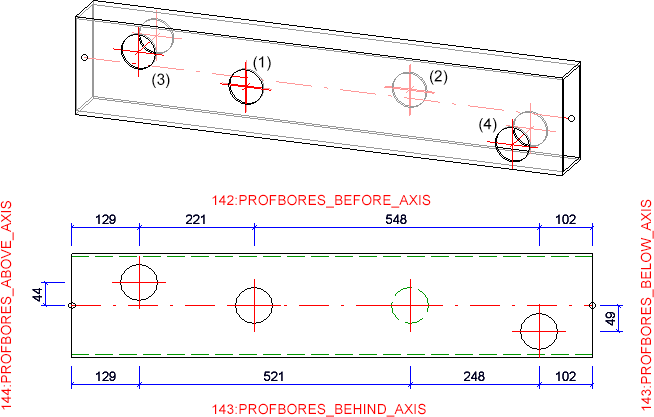
142 |
Beam processings, located in front of the axis of the main part |
PROFBORES_BEFORE_AXIS The rules 142-145 create separate chains of dimensions depending on the position of the processing with regard to the beam axis. If perpendicular dimensions should be extended to the left or right depending on the processing regarding the beam middle, this can be done by selecting Position:Automatic.
|
|
143 |
Beam processings, located behind the axis of the main part |
PROFBORES_BEHIND_AXIS |
|
144 |
Beam processings, located above the axis of the main part |
PROFBORES_ABOVE_AXIS |
|
145 |
Beam processings, located below the axis of the main part |
PROFBORES_BELOW_AXIS |
|
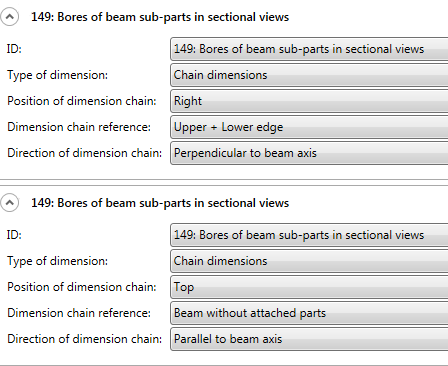
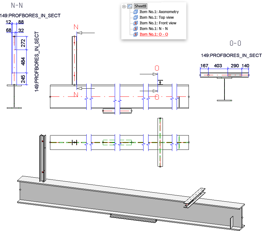
149 |
Bores of beam sub-parts in sectional views |
PROFBORES_IN_SECT |
|
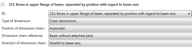
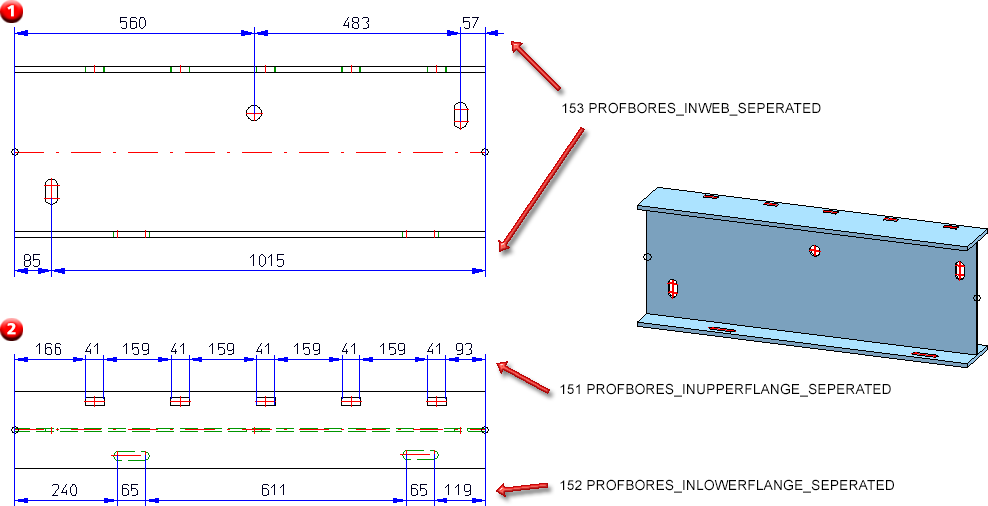
151 |
Bores in upper flange of beam, separated by position with regard to beam axis |
PROFBORES_INUPPERFLANGE_SEPERATED |
|
152 |
Bores in lower flange of beam, separated by position with regard to beam axis |
PROFBORES_INLOWERFLANGE_SEPERATED |
|
153 |
Bores in web of beam, separated by position with regard to beam axis Rules 151, 152 and 153 only apply for dimensioning parallel to the beam axis, since other separation mechanisms exist for dimensionings perpendicular to the beam axis. Only bores that are located in the view plane will be considered. If Position of dimension chain: Automatic has been selected, the chains will be pulled out upwards or downwards, depending on the position of bores. |
PROFBORES_INWEB_SEPERATED |
|
Value |
Description |
Designation / Rule Identifier |
|---|---|---|
|
29 |
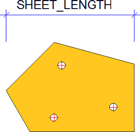
Sheet/plate length |
SHEET_LENGTH |
|
30 |
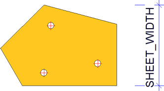
Sheet/plate width |
SHEET_WIDTH |
|
31 |
Sheet/plate thickness |
SHEET_THICKNESS |
|
47 |
Length of sheets/plates (sub-parts) in sectional views |
SHEET_LENGTH_IN_SECT |
|
48 |
Width of sheets/plates (sub-parts) in sectioanl views |
SHEET_WIDTH_IN_SECT |
|
Value |
Description |
Designation / Rule Identifier |
|---|---|---|
|
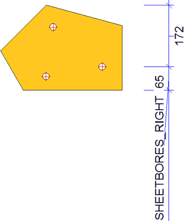
32 |
Bores in sheets/plates, right side |
SHEETBORES_RIGHT |
|
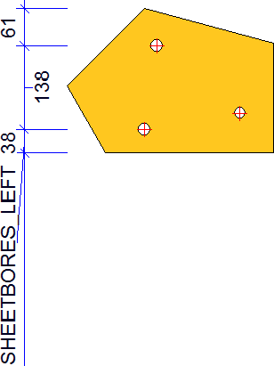
33 |
Bores in sheets/plates, left side |
SHEETBORES_LEFT |
|
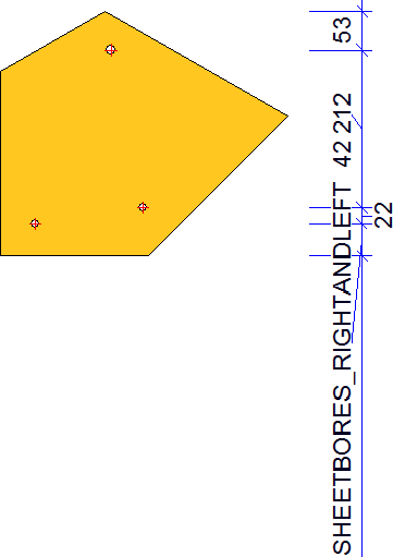
34 |
Bores in sheets/plates, right or left side |
SHEETBORES_RIGHTANDLEFT |
|
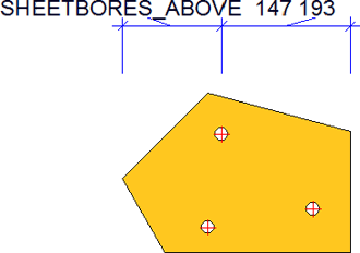
35 |
Bores in sheets/plates, upper half |
SHEETBORES_ABOVE |
|
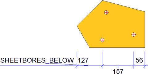
36 |
Bores in sheets/plates, lower half |
SHEETBORES_BELOW |
|
37 |
Bores in sheets/plates, upper or lower half |
SHEETBORES_ABOVEANDBELOW |
|
38 |
Outer contour of sheet/plate, right side |
SHEETOUTLINE_RIGHT |
|
39 |
Outer contour of sheet/plate, left side |
SHEETOUTLINE_LEFT |
|
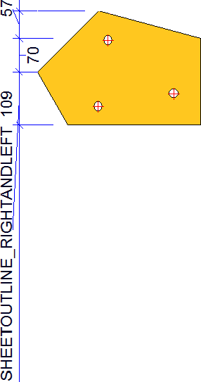
40 |
Outer contour of sheet/plate, right or left side |
SHEETOUTLINE_RIGHTANDLEFT |
|
41 |
Outer contour of sheet/plate, upper half |
SHEETOUTLINE_ABOVE |
|
42 |
Outer contour of sheet/plate, lower half |
SHEETOUTLINE_BELOW |
|
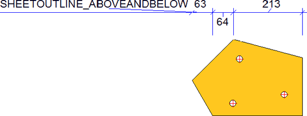
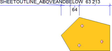
43 |
Outer contour of sheet/plate, upper or lower half |
SHEETOUTLINE_ABOVEANDBELOW |
|
49 |
Outer contour of sheets/plates, right and left side, in sectional views |
SHEETOUTLINE_RIGHTANDLEFT_IN_SECT |
|
50 |
Outer contour of sheets/plates (sub-parts), top and bottom side, in sectional views |
SHEETOUTLINE_ABOVEANDBELOW_IN_SECT |
|
51 |
Bores in sheets/plates (sub-parts), right or left side, in sectional views |
SHEETBORES_RIGHTANDLEFT_IN_SECT |
|
52 |
Bores in sheets/plates (sub-parts), top and bottom half, in sectional views |
SHEETBORES_ABOVEANDBELOW_IN_SECT |
|
60 |
Fillet radii on outer contours of sheets/plates |
SHEETOUTLINE_RADIUS |
|
61 |
Fillet radii on material subtractions on sheets/plates |
SHEETBORES_RADIUS |
|
62 |
Fillet radii on outer contours of sheets/plates in sectional views |
SHEETOUTLINE_RADIUS_IN_SECT |
|
63 |
Fillet radii on material subtractions on sheets/plates in sectional views |
SHEETBORES_RADIUS_IN_SECT |
|
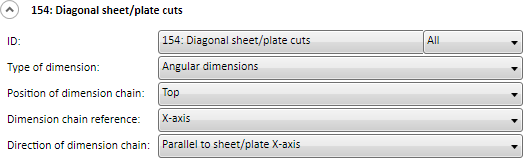
154 |
Diagonal sheet/plate cuts |
SHEET_DIAGONAL_CUT |
|
Value |
Description |
Designation / Rule Identifier |
|---|---|---|
|
44 |
Diameter of simple bores in main part |
BORE_DIAMETER_MAINPART |
|
45 |
Diameter of standard part bores in main part |
NORMBORE_DIAMETER_MAINPART |
|
46 |
Diameter of boltings in main part |
CONNECTION_DIAMETER_MAINPART |
|
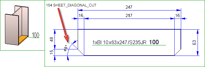
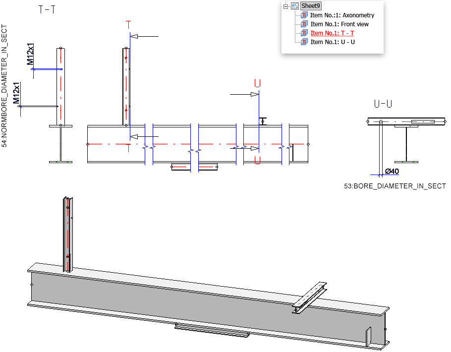
53 |
Diameters of simple bores in sheets/plates (sub-parts) in sectional views |
BORE_DIAMETER_IN_SECT |
|
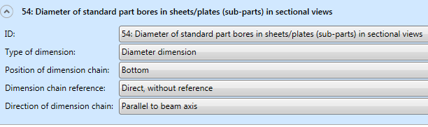
54 |
Diameter of standard part bores in sheets/plates (sub-parts) in sectional views |
NORMBORE_DIAMETER_IN_SECT |
|
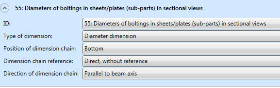
55 |
Diameters of boltings in sheets/plates (sub-parts) in sectional views |
CONNECTION_DIAMETER_IN_SECT |
|
Value |
Description |
Designation / Rule Identifier |
|---|---|---|
|
76 |
Length of beam sub-parts |
PROFILELENGTH_ATTACHING_PROFILES Sub-part lengths of all (also oblique) sub-parts |
|
77 |
Connected beam sub-parts |
CONNECTED_PROFILES Start and end of all direct connections of sub-parts to main part |
|
80 |
Connected sub-part beams on relevant beams |
CONNECTED_PROFILES_RELEVANTPROFILES Start and end of all direct connections of sub-parts to relevant parts |
|
94* |
All attached parts of relevant beam sub-parts, via outer contour |
ATTACHING_PARTS_RELVPROFS |
|
96* |
Attached Sheet Metal parts with bores on relevant beam sub-parts |
ATTACHING_SHEETS_RELVPROFS |
|
105 |
Attached plates/sheets on relevant beam sub-parts; one dimension chain for each plate/sheet |
ATTACHING_SHEETS_SEPERATELY_RELVPROFS |
|
106 |
Attached plates/sheets on upper beam sides on relevant beam sub-parts; via bores or outer contour |
ATTACHING_SHEET_UPPERSIDE_RELVPROFS |
|
107 |
Attached plates/sheets on lower beam sides on relevant beam sub-parts; via bores or outer contour |
ATTACHING_SHEET_LOWERSIDE_RELVPROFS |
|
108 |
Attached plates/sheets on web surface on relevant beam sub-parts, before web, via bores or outer contour |
ATTACHING_SHEET_BEFORE_WEB_RELVPROFS |
|
109 |
Attached plates/sheets on web surface on relevant beam sub-parts, after web, via bores or outer contour |
ATTACHING_SHEET_BEHIND_WEB_RELVPROFS |
|
110* |
Attached parts on relevant beam sub parts |
ATTACHING_PROFILES_VERT_RELVPROFS |
|
112 |
Angle between relevant beams and connected sub-part beams |
STWDimRuleIdent_ANGLE_CONNECTED_PROFILES_RELPROFS |
*see Notes on the dimensioning rules
|
Value |
Description |
Designation / Rule Identifier |
|---|---|---|
|
98 |
Bores in web of relevant beam sub-parts |
PROFBORES_INWEB_RELVPROFS |
|
99 |
Bores in upper flange of relevant beam sub-parts |
PROFBORES_INUPPERFLANGE_RELVPROFS |
|
100 |
Bores in lower flanges of relevant beam sub-parts |
PROFBORES_INLOWERFLANG_RELVPROFS |
|
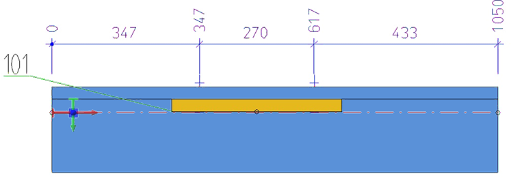
101 |
Bores in flanges of relevant beam sub-parts |
PROFBORES_INFLANGES_RELVPROFS |
|
Value |
Description |
Designation / Rule Identifier |
|---|---|---|
|
132 |
Sheet length |
SHEETMETAL_LENGTH |
|
133 |
Sheet width |
SHEETMETAL_WIDTH |
|
134 |
Sheet height |
SHEETMETAL_HEIGHT |
|
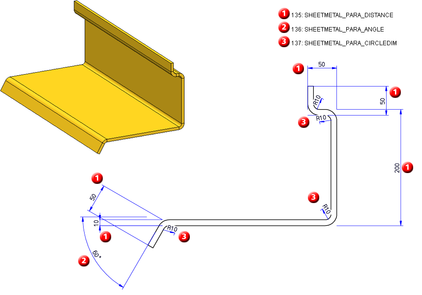
135 |
Parametric linear dimensions of sheets |
SHEETMETAL_PARA_DISTANCE |
|
136 |
Parametric angular dimensions of sheets |
SHEETMETAL_PARA_ANGLE |
|
137 |
Parametric circular dimensions of sheets |
SHEETMETAL_PARA_CIRCLEDIM |
|
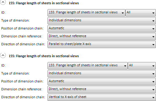
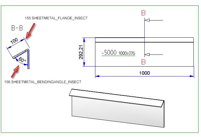
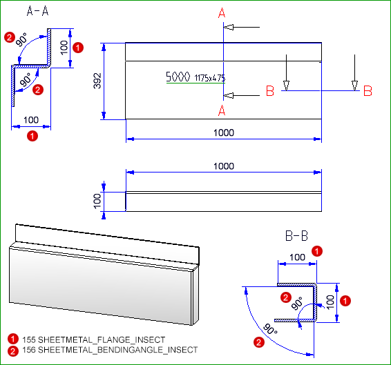
155 |
Flange length of sheets in sectional views |
SHEETMETAL_FLANGE_INSECT |
|
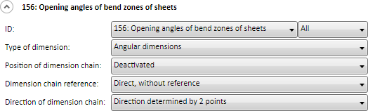
156 |
Opening angles of bend zones of sheets |
SHEETMETAL_BENDINGANGLE_INSECT |
|
Value |
Description |
Designation / Rule Identifier |
|---|---|---|
|
1001 |
Total length of Railing segment assembly |
TOTAL_LENGTH_RAILINGSEGMENT only for Railing segment assembly: |
|
1002 |
Total height of Railing segment assembly |
TOTAL_HEIGHT_RAILINGSEGMENT only for Railing segment assembly: |
|
1003 |
Total length of Railing segment assembly w/o base plates |
TOTAL_LENGTH_RAILINGSEG_WITHOUT only for Railing segment assembly: |
|
1004 |
Total height of Railing segment assembly w/o base plates |
TOTAL_HEIGHT_RAILINGSEG_WITHOUT only for Railing segment assembly: |
|
1005 |
Total dimension of Railing segment assembly |
TOTAL_SIZE_RAILINGSEGMENT only for Railing segment assembly: |
|
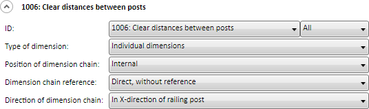
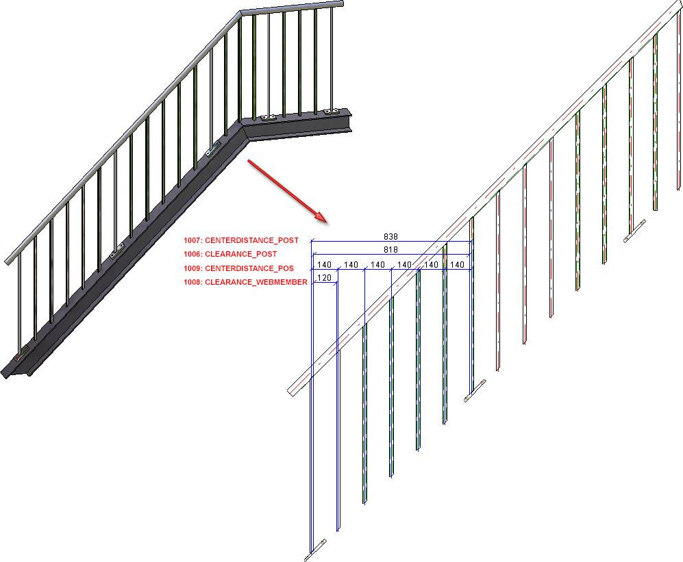
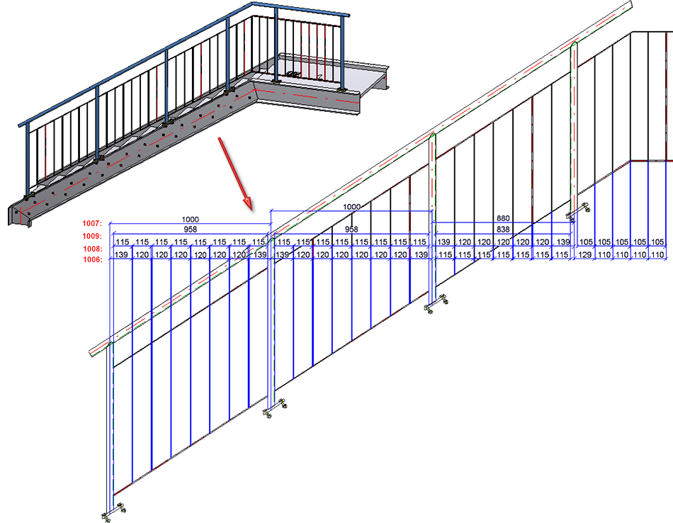
1006 |
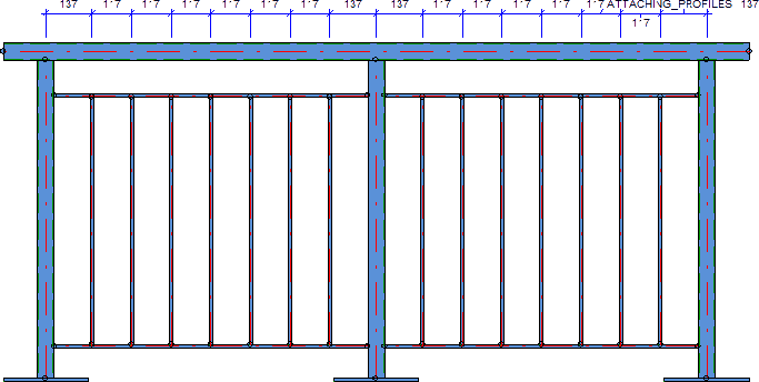
Clear distances between posts If the clear distance between two posts is dimensioned as individual dimension, the post thickness will not be considered. The dimensioning takes places in all fields of the railing segments. If the dimensions of the rule are not equal in all fields, only the dimension of the first field will be depicted. In dimension type Chain of dimensions the post thickness will be taken into consideration, too. If the chain of dimensions of all fields is equal, only the chain of dimensions of the first field will be depicted. |
CLEARANCE_POST only for Railing segment assembly: The depiction shows a staircase with equal distance between post and following vertical rod as well as between the vertical rods. The thickness of post and vertical rod are identical. The dimension and chain of dimensions of rules 1006-1009 are equal for each field.
The oblique segment of the depicted staircase has individual distances for posts and vertical rods as well as different post and vertical rod thickness. Hence, dimension and chain of dimensions of rules 1006 to 1009 are not equal.
|
|
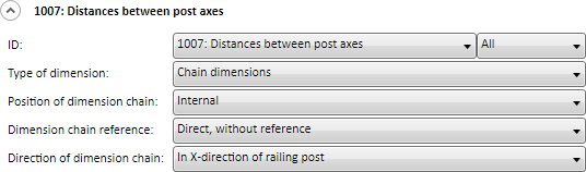
1007 |
Distances between post axes The axis distance of two posts is dimensioned in all fields of the railing segment. If the dimensions of this rule are equal in each field, only the dimension of the first field will be depicted. |
CENTERDISTANCE_POST only for Railing segment assembly: |
|
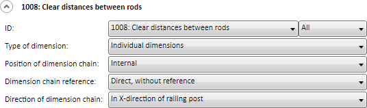
1008 |
Clear distances between rods If the clear distance between two posts is dimensioned as Individual dimension, the post thickness will not be considered. The dimensioning takes places in all fields of the railing segments. If the dimensions of the rule are not equal in all fields, only the dimension of the first field will be depicted. Recommended setting for rule 1008
In dimension type Chain of dimensions the post thickness will be taken into consideration, too. If the chain of dimensions of all fields is equal, only the chain of dimensions of the first field will be depicted. |
CLEARANCE_WEBMEMBER only for Railing segment assembly: |
|
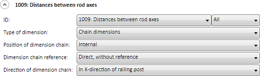
1009 |
Distances between rod axes This rule dimensions the axis distance between posts and vertical rods as chain of dimensions. The dimensioning takes place in all fields of the railing segment. If the dimensions of the rule are not equal in all fields, only the dimension of the first field will be created.
|
CENTERDISTANCE_WEBMEMBER only for Railing segment assembly: |
|
1010 |
Hand rail excess length |
HANDRAIL_PROJECTION only for Railing segment assembly: |
|
1011 |
Sub-parts |
RAILING_SUBPARTS only for Railing segment assembly: |
|
1012 |
Sub-parts, Post assembly |
POST_SUBPARTS only for Railing segment assembly: |
|
1013 |
Sub-parts, Infill assembly |
FILLING_SUBPARTS only for Railing segment assembly: |
|
1014 |
Angle Post - Handrail |
ANGLE_POST_HANDRAIL only for Railing segment assembly: |
|
1015 |
Bores |
RAILING_BORES only for Railing segment assembly: |
Example 2:
The oblique segment of the depicted staircase has individual distances for posts and vertical rods as well as different post and vertical rod thickness. Hence, dimension and chain of dimensions of rules 1006 to 1009 are not equal.
(Dies ist der Dropdown-Text)
In the file STW_DIMSETTINGS.XML you can specify how base points on hidden parts are to be handled when using dimensioning rules. To do this, enter the following string into the file:
</PARAM><PARAM Name="IGNOREHIDDENSUBPARTANDBORES" Typ="INT" Value="0">
If Value has been set to 1, base points that are located on hidden sub-parts will not be considered for dimensioning in all dimensioning rules.
When dimensioning attached sheet/plate parts or plates and beams that border on dimensionally relevant beams, both contact points will always be dimensioned. If only the first contact point in the chain is to be dimensioned, open the STW_DimSettings.XML (conventional dimensioning settings) file in the HiCAD sys directory and set the parameter
</PARAM><PARAM Name="SUBPARTPOSITION" Typ="INT" Value="0">
to 1.
This setting affects all dimensioning rules marked with an asterisk *.
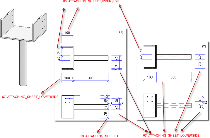
Example - (1) without change of the STW_DimSettings.XML , (2) with change of the STW_DimSettings.XML
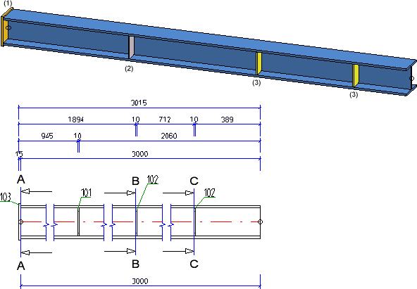
You have the option to create separate chain dimensions per different usage for chain dimensions describing the fitting situation of parts. To change this behaviour, open the STW_DimSettings.XML (conventional dimensioning settings) file in the HiCAD sys directory and set the parameter SEPERATEDSUBPARTPOSITION to 1:
</PARAM><PARAM Name="SEPERATEDSUBPARTPOSITION" Typ="INT" Value="1">
The image below shows a beam with 4 plates for different usages (1=Front plate, 2=Reinforcement plate, (3) Stiffener) and the front view of the production drawing.
If the STW_DimSettings.XML file does not contain the described parameters, you can also make manual entries as described above.
In the Dimensioning Settings it is now possible to determine under Bores/Boltings that separate chains of dimensions should be created for bores (through holes and standard bores) and subtractions. For this purpose there is the Separate dimension chains for bores and subtractions checkbox.
For new installations or when the dimensioning settings file STW_DIMSETTINGS.xml is not yet available, the stab3par.dat option can be switched on and off under
Maßketten für Lage der Bohrungen/Ausnehmungen trennen nach Bohrungen und Ausnehmungen 1:ja, 0:nein
If the STW_DIMSETTINGS.xml file is available, the line
</PARAM><PARAM Name="DEVIDEBORESANDCUTS" Typ="INT" Value="1">
has to be added.
This settings will not yet be saved in the workshop drawing at this point!
Please note that this setting also affects the following dimensioning rules:
|
12 |
Bores in web of beam |
PROFBORES_INWEB |
|
15 |
Bores in upper and lower flange of beam |
PROFBORES_INFLANGES |
|
34 |
Bores in sheets/plates, right or left side |
SHEETBORES_RIGHTANDLEFT |
|
37 |
Bores in sheets/plates, upper or lower half |
SHEETBORES_ABOVEANDBELOW |
|
49 |
Outer contour of sheets/plates, right and left side, in sectional views |
SHEETOUTLINE_RIGHTANDLEFT_IN_SECT |
|
50 |
Outer contour of sheets/plates (sub-parts), top and bottom side, in sectional views |
SHEETOUTLINE_ABOVEANDBELOW_IN_SECT |
|
85 |
Beam processing in web, incl. processings in side view |
PROFBORES_INWEB_VERT |
|
88 |
Beam processings in upper and lower flange, incl. processings in side view |
PROFBORES_INFLANGES_VERT |
|
98 |
Bores in web of relevant beam sub-parts |
PROFBORES_INWEB_RELVPROFS |
|
101 |
Bores in flanges of relevant beam sub-parts |
PROFBORES_INFLANGES_RELVPROFS |
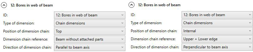
Example - Separate chains of dimensions for bores and subtractions
The depicted drawing (1) contains several through holes bores and one rectangular subtraction. (2) separate chains of dimension, (3) one chain of dimensions for bores and subtractions
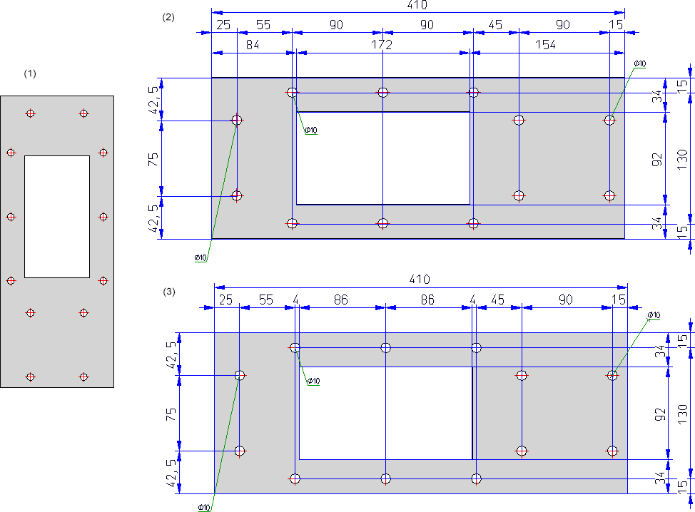
In the example the following settings for dimensioning rule 12 have been used for (3):
In the Dimensioning Settings it is now possible to determine under General that attached parts (beams) will be dimensioned according to the Part type attribute in the different chains of dimensions. A respective checkbox is available in the dialogue window. In this way it is possible to dimension hollow profiles / attached parts separately from round steel / attached part, thus improving the dimension structure.
This setting affects dimensioning rules for chains of dimensioning of relevant parts.
For new installations or when the dimensioning settings file STW_DIMSETTINGS.xml is not yet available, the stab3par.dat option can be switched on and off under
Separated chain dimensions according to part type for position of sub-parts 1:yes, 0:no - Getrennte Massketten nach Teileart fuer Einbausituation von Nebenteilen 1:ja, 0:nein
If the STW_DIMSETTINGS.xml file is available, the line
</PARAM><PARAM Name="SEPERATEDSUBPARTPOSITION_PT" Typ="INT" Value="0">
has to be added.

Drawing Derivation • Derived Drawings: Settings • Drawing Derivation: Dialogue Window
|
© Copyright 1994-2018, ISD Software und Systeme GmbH |