> Dimensioning Settings
Drawing > Itemisation/Detailing > Dim. > Dimensioning Settings
For drawing derivations, the dimensioning of parts and assemblies normally takes place according to the dimensioning rules specified in the Configuration Editor (isdconfigeditor.exe) for the different usages. These settings apply even if the Drawing parameters: Set in dialogue option has been activated in the dialogue window for drawing derivations.
If you do not want to use this dimensioning rule but the conventional dimensioning rule, you need to change the Usage configurations accordingly.
In the Configuration Editor, select ..> Automatic drawing derivation > Production drawing > Usage-dependent > NAME > Views, with NAME being the name of the corresponding usage, i.e. for example ASSEMBLY_BEAM, and set the Create dimensioning parameter to Conventional.
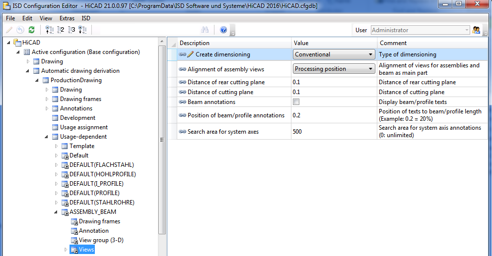
If the parameter is set to Conventional, not the settings in the Configuration Editor, but the conventional dimensioning settings from the STW_DimSettings.xml file in the HiCAD sys directory will be used.
This concerns:
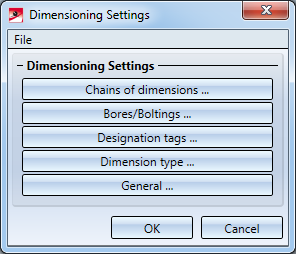
When you call the function the Dimensioning Settings window is displayed. Select which settings window you want to activate by clicking the appropriate button.
![]()
In order to deactivate the dimensioning of 90° bend angle, currently the system files
must be adjusted manually.
STAB3DPAR.DAT
Here, the setting is done via
Display right angle for opening angle of bend zones of sheet metal? 1:yes, 0:no
0
STW_DIMSETTINGS.XML
Here, deactivating the dimensioning is done via line
</PARAM><PARAM Name="SHOWRIGHTANGLEOFBENDZONE" Typ="INT" Value="0">
If this line is not available it must be added manually.

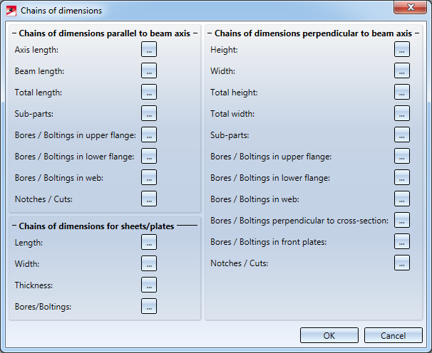
The Chains of dimensions window enables you to individually specify for:
to which views you want to apply the dimensionings. Click the Select views... button to the right of the appropriate entry and select the desired views by activating or deactivating the corresponding checkboxes.
When you exit the window with OK, the Settings for dimensioning window is displayed again.
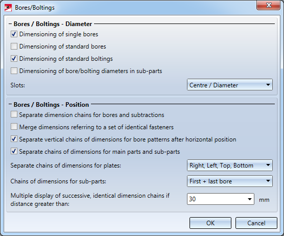
In this dialogue window you specify which bore and bolting diameters you want to dimension, and the way in which you want to dimension slots: Do not dimension, Length/Width or Centre/Diameter.
In addition, you can influence the position of dimensionings for bores/boltings. You can, for instance, specify whether you want to separate chains of dimensions for main parts and sub-parts, etc. Moreover, you can determine that separate chains of dimensions for bores (through holes and standard bores) and subtractions should be created.
When you exit the window with OK, the Settings for dimensioning window is displayed again.
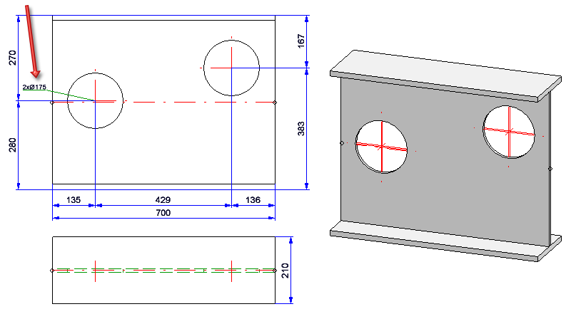
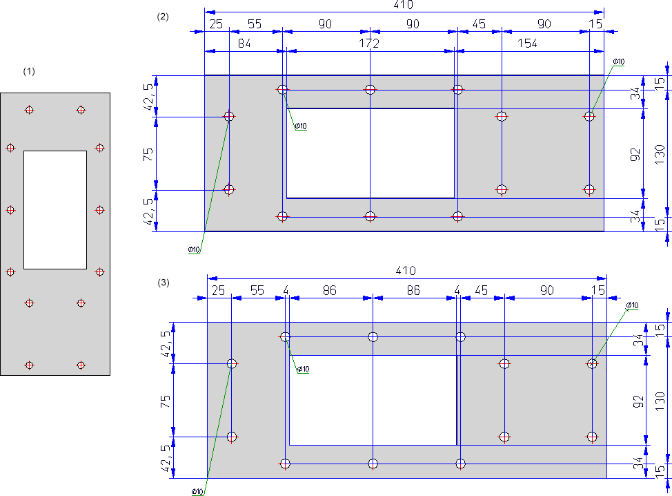
Example - Separate chains of dimensions for bores and subtractions
The depicted drawing (1) contains several through holes bores and one rectangular subtraction. (2) separate chains of dimension, (3) one chain of dimensions for bores and subtractions
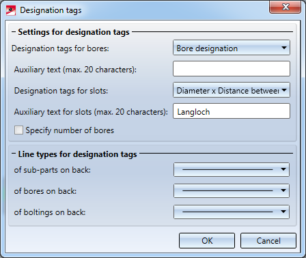
This function enables you to define various settings for the designation tags in a workshop drawing.
For example, you can select for bore designation tags whether you want to use the designation for the bore or for the appropriate bolt. Furthermore, you can add an auxiliary text consisting of up to 20 characters and you can determine whether the number of bores is specified or not.
If the Specify number of bores checkbox is activated, bores which are the same but do not belong to the same bore pattern will be combined.
However, this will only apply under the following conditions:
In the lower part of the dialogue window you can select a different line type for the designation tag for sub-parts, bores or boltings on the back of a part.
The checkbox next to the respective selection box determines whether the designation tabs of sub-parts, bores and boltings on the back of the part will be displayed or not. The checkbox is activated by default, i.e. the designation tabs will be displayed.
Deactivating the bores checkbox makes sense e.g. in the hidden line mode, as the bores are not visible in this case, hence it does not make sense to label them. This setting affects not only conventional dimensioning but also the dimensioning rules.
When you exit the window with OK, the Settings for dimensioning window is displayed again.
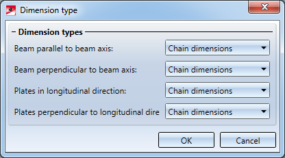
Use this function to specify the type of dimensioning in the workshop drawing. Possible are:
The selection can be separately applied to
When you exit the window with OK, the Settings for dimensioning window is displayed again.
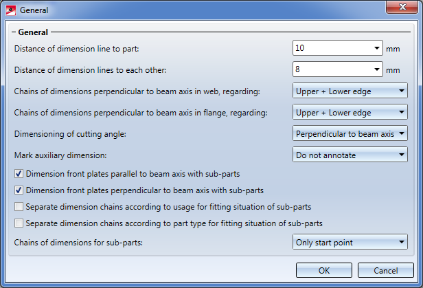
Use this function to define general settings.
Examples are:
Furthermore you can determine
When you exit the window with OK, the Dimensioning Settings window is displayed again.

Drawing Derivation • Derived Drawings: Settings • Drawing Derivation: Dialogue Window
|
© Copyright 1994-2018, ISD Software und Systeme GmbH |