Werkstattzeichnungerstellen
Drawing > Itemisation/Detailing > Drawing derivation 
Use this function to derive a new technical drawing from your 3-D model drawing, e.g. a workshop drawing.
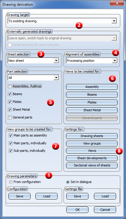
When you call the function, the Derived drawing dialogue window will be displayed:

Proceed as follows:
- If you want to use an already existing settings file or configuration, select and load one. Change the settings in the dialogue window if desired.
- Select the Drawing target for the workshop /detail drawing creation from the listbox.
- In the Sheet selection area, specify whether you want the output to be made to a new sheet or to an already existing sheet.
- Select the desired Alignment of assemblies: In processing position or fitting position ("ready-to-use position").
- In the Part selection area, specify the part types you want to take over into the workshop drawing, either via selection from the list box or by activating the appropriate checkboxes.
- Specify the Views to be created fro assemblies, beams, plates and sheets.
- Specify the View groups to be created by activating the appropriate checkboxes.
- Specify the Settings for drawing sheets, view groups, views, sheet developments and sectional view of sheets as required.
The specified settings can be saved and reused later if desired. You can also create several settings files, e.g. settings for particular customers, or for particular tasks such as detail drawings for assemblies and detail drawings for sub-parts.
Please remember that the current settings in the dialogue window are only temporary (i.e. for the current HiCAD session) default settings. Close the window with OK. If you have chosen the option Part selection: Select individual, HiCAD will prompt you to identify the parts for the workshop drawing. Press the middle mouse button to end the selection.
The derived drawing will be automatically created as a sheet view - either in the original model drawing or in a new model drawing - and can then be opened via the Views tab in the ICN.
Example:
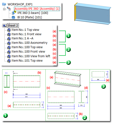
The following example shows an assembly consisting of one beam and one plate, and the example of a workshop drawing consisting consisting of three view groups. Group 1 contains the assembly views, Group 2 the beam views and Group 3 the plate views.

 If you are using with the Steel Engineering suite premium in conjunction with HELiOS Engineer, please always observe the information given in the Steel Engineering Drawing Management Help! On the Management + BIM tab that has been especially designed for civil engineering design tasks, you can find various BIM-PDM functions as well as functions for itemisation, workshop drawing generation, BOM generation, etc. Furthermore, you are enabled to automatically configure HiCAD title blocks, drawing frames, BOM templates and HELiOS masks for the management of Steel Engineering drawings.
 Please note:
- To create a workshop drawing of the current steel engineering drawing, first select the
Itemisation function to itemise the parts of the drawing. If the drawing contains non-itemised parts when you select the Derived drawing function, you can ignore these parts or re-itemise them. In such cases HiCAD will issue an appropriate message.
- The inserted sheet views can be deleted via the context menu for views - either in the ICN or in the drawing.
- View groups are displayed with a rectangular frame enclosing all views of the group. This frame can be automatically adjusted to the size of the view group with the Update derived drawing function.
- When you call the function again, the last saved settings will be active in the derived drawing dialogue windows. If you want to subsequently change the settings of an already existing drawing, use the Derive
 > Change settings functions.
- To arrange view groups, select Views > View Functions > Others > Arrange view group.
- When creating a workshop drawing, the current projection/position is captured as the required position, thus enabling you to restore the original view at any time after rotating the view.
- Assemblies, sheets and general parts must be BOM-relevant; otherwise they will not be included in the workshop drawing.
- For annotations in workshop drawings, the FTD files will be evaluated according to the current settings in the Configuration Editor, at Automatic drawing derivation > Production drawing > Usage-dependent > name > Annotation . name is the name of the corresponding usage.
- If the model drawing contains connecting elements that have been created with the Metal Engineering functions 3-D section, these will not be considered in the workshop drawing - even if these elements are BOM-relevant.
- Assembly points will be generally hidden in the derivation of production drawings.
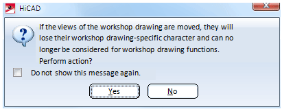
 If you move a view from one sheet of the workshop drawing to another (via Drag & Drop), HiCAD will issue the following message:

After performing the action, the corresponding views will no longer be considered for the updating of the workshop drawing.


Derived Drawing: Functions • Derived Drawing: Change Settings • The 'Derive Drawing' Dialogue Window • Derived Drawing - Settings File or Configuration • Usage-Dependent Configuration
|
© Copyright 1994-2018, ISD Software und Systeme GmbH
Version 2302 - HiCAD Basics
Date: 30/10/2018
|
> Feedback on this topic
|


 If you are using with the Steel Engineering suite premium in conjunction with HELiOS Engineer, please always observe the information given in the Steel Engineering Drawing Management Help! On the Management + BIM tab that has been especially designed for civil engineering design tasks, you can find various BIM-PDM functions as well as functions for itemisation, workshop drawing generation, BOM generation, etc. Furthermore, you are enabled to automatically configure HiCAD title blocks, drawing frames, BOM templates and HELiOS masks for the management of Steel Engineering drawings.
 ![]() Please note:
Please note: > Change settings functions.
  If you move a view from one sheet of the workshop drawing to another (via Drag & Drop), HiCAD will issue the following message:
