2-D Part Properties > Attr.

3-D Standard > Tools > Attr.
Every 2-D and 3-D part has certain properties. These include attributes, which influence the appearance and shape of the part and its geometry elements, and non-graphical information, which is taken into account, for example, in BOM creation. A distinction is made here between element or line attributes and the part properties and attributes.
The element attributes - colour, line type and layer - influence the display of individual geometry elements of a part. You can use these attributes, for example, to hide parts of your drawing temporarily, which may be useful for editing complex drawings in many cases. You can easily change the element and line attributes in Element snap mode by right-clicking the relevant element and then choosing Properties in the context menu.
Part properties describe the actual part. 2-D part properties include, for example, the overlap level or the material. The material, the surface and the part variables are examples of 3-D part properties. Furthermore, you can assign 2-D and 3-D parts other non-graphical information, the so-called part attributes, which is taken into account, for example, in BOM creation. Examples include the number, item, description or part type. This is particularly relevant if you are working without the PDM system HELiOS.
To change the properties of a part, proceed as follows:
For active parts these functions are also available on the 2-D Part and 3-D Standard tabs:
|
|
2-D Part Properties > Attr. |
|
|
3-D Standard > Tools > Attr. |
Clicking  opens a pull-down menu with further functions.

2-D Part Attributes  / 3-D Part Attributes
You use the Part attributes function to assign a part non-graphical attributes, e.g. number, position, designation or part type, which are taken into account in BOM creation. This is particularly relevant if you are working without the HELiOS PDM functions.
The function is available in the context menu as well as in the 2-D Part and 3-D Standard tabs.
![]() Please note:
Please note:
 During automatic itemisation you can automatically assign the types of use Girder (beam) assembly or Column assembly to Steel Engineering assemblies. For this to happen, open the Configuration Editor and set the parameter at Steel Engineering > Types of use accordingly.
Please note that the calculation of this value depends on the setting in the Configuration Editor, at Modelling > Part properties > Calculate quantity in assembly.
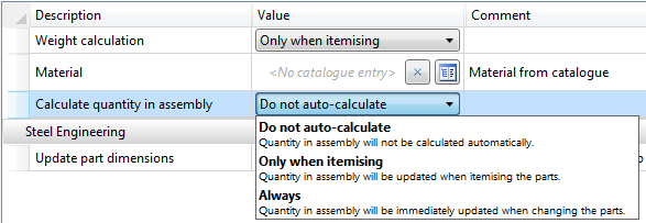
The default setting is Do not auto-calculate. If the value is to be automatically calculated, we recommend choosing the Only when itemising option. As the calculation refers to the item numbers, items without valid item numbers will have no effect.
Example:
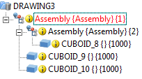
A drawing contains one assembly with three identical parts, one of which belongs to a subordinate assembly:
|
|
Part attribute |
|
|
|
Quantity in |
Total |
|
|
CUBOID_8 |
1 |
3 |
|
|
CUBOID_9 |
2 |
3 |
|
|
CUBOID_10 |
2 |
3 |
|
This part attribute can, for instance, be used for annotations or in BOMs.
If a drawing is active that has been created with the functions of the Management + BIM module, the Item number field in the Part attributes dialogue window will be locked.

ICN • Bills of Materials (BOMs) • HELiOS PDM Functions • System Attributes
|
© Copyright 1994-2018, ISD Software und Systeme GmbH |