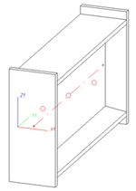
Assemblies are marked in the drawing by means of large red isolated points. These points can be used to identify an assembly directly in the drawing.

The assembly points can directly be determined when creating a new assembly. HiCAD automatically sets the assembly points during automatic forming of assemblies in Steel Engineering drawings (e.g. for connections). This also applies if you use the Form assembly function to create an assembly from already existing Steel Engineering parts.
Use the functions of the Assembly points menu to change or add assembly points.
You can access the Assembly points menu by right-clicking either the assembly in the ICN or an assembly point in the drawing.
The following functions are available:
 Please note:
 > Assembly points ON
  or Assembly points OFF
  , respectively.
 When creating new assemblies, forming assemblies from existing parts and automatically creating assemblies (e.g. for Steel Engineering), the prefix Assembly will be suggested as the default value for the article number. This setting can now be changed in the Configuration Editor at Steel Engineering > Assembly.

The ISD default setting is the text stored in the HiCAD text key TEXTE_STB325 , i.e. the string "Assembly".
If you want to use your own text instead, simply enter it into the field after deactivating the Text key checkbox.
 This setting cannot be applied to main assemblies.

|
© Copyright 1994-2018, ISD Software und Systeme GmbH |