 symbol in the ICN and have the part type Assembly.
 The Main assembly is a special assembly to which all assemblies and parts belonging to a product are subordinated. Each 3-D drawing can contain only one main assembly. However, this does not mean that the drawing cannot contain further, individual parts and assemblies in parallel with the Main assembly. If on-site elements are involved, in addition to the product to be supplied, as is often the case with mixed constructions involving various industries, these on-site elements will not be located in the main assembly, but as individual parts or assemblies on the same level as the Main assembly.
Thus the main assembly is the top assembly in the model drawing and can in turn consist of various assemblies. The assemblies, too, consist of individual parts (Main parts and Sub-parts).
For 3-D Drawings HiCAD offers the option to define the drawing directly as an assembly drawing upon its creation and, if applicable, enter it into the HELiOS database. To do this, activate the Create new drawing (3-D Assembly) option in the Start Centre. For a 3-D assembly drawing, HiCAD automatically creates a 3-D main assembly to which all subsequently created 3-D assemblies and parts will be assigned!
3-D Drawings can also be subsequently converted into assembly drawing if desired. Main assemblies are used in numerous automatisms in HiCAD. For example, the product structure of the main assembly will be automatically transferred, including its sub-assemblies, to the HELiOS product structure when performing itemisations or identical part search in Steel Engineering.
3-D Main assemblies are marked with the  symbol in the ICN and have the part type Assembly.
The utilisation of main assemblies is not mandatory, but recommended, as it provides much more efficiency, most notably for referencing, itemisation, BOM creation and the combined working with the PDM system HELiOS.

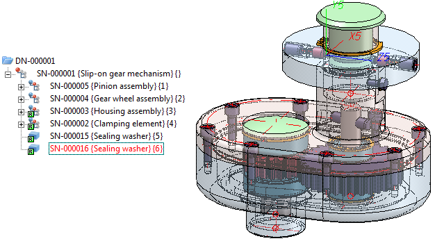
Model drawing of a slip-on gear mechanism, consisting of one main assembly, several assemblies and individual parts
![]() Please note:
Please note:
In contrast to 3-D, there are no special main assemblies in 2-D. Here, only main parts and sub-parts are normally used.
But of course, you can simply rename a 2-D Main part (e.g. to Main assembly motor), or a 2-D Sub-part (e.g. to Assembly Sheet cladding).
In addition, you have the option to combine all parts of the current drawing into a so-called 2-D main assembly. To do this, use the Main assembly (2-D)  function in the New function group on the 2-D Part tab.
All parts that exist in the drawing at this point will then be automatically subordinated to this main assembly. This means that a 2-D drawing can, in contrast to a 3-D drawing, contain more than one main assembly.

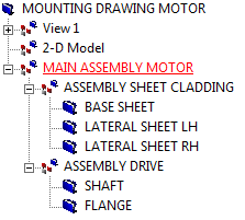
Structure of a 2-D mounting drawing with one main assembly consisting of two sub-assemblies that in turn contain three and, respectively, two parts

Part Drawing or Assembly Drawing • Part Structure: Advantages and Planning
|
© Copyright 1994-2018, ISD Software und Systeme GmbH |