Rules for the creation of Feature Variants for Plant Engineering parts
|
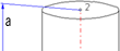
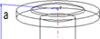
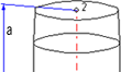
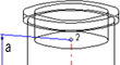
Position of connecting points and determination of insertion lengths for various connection types |
|||
|---|---|---|---|
|
Connection for butt welding |
Flange connection |
Connecting nipple for |
Connecting socket for |
|
|
|
|
|
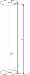
| a = Insertion length dimension (e.g. L, L1 etc.) |
a = Insertion length dimension (e.g. L, L1 etc.) |
a = Insertion length dimension (e.g. L, L1 etc.) |
a = Insertion length dimension (e.g. L, L1 etc.) |
Named isolated points
|
Designation |
Purpose |
Comment |
Position in coordinate system |
|---|---|---|---|
|
! |
Connecting point |
Fitting point |
In origin (0,0,0) |
|
2 |
Connecting point |
|
X = 0, Y = 0, Z > 0 |
|
Name |
Description |
Attribute (optional) |
|---|---|---|
|
L |
Distance between point “!“ and “2“ |
LAENGE |
If the variables names given in the Name column are used, you do not need to assign any attributes to them via the Variant Editor. If different variables are required, you need to assign the attributes given in the Attribute column.
VAA file
Use the Variant Editor to enter the suitable part type into the VAA file.
Then, use the Variant Editor to expand the VAA file in such a way that it contains values for the sizes specified here, and that the predefined attribute assignment is entered:
|
Parameter All dimensions must be specified in millimetres; |
Variable |
Assigned attribute |
|---|---|---|
|
Nominal width, Connection “!“ and “2“ |
N |
NENNWEITE |
|
Length |
L |
LAENGE |
|
|
||
|
Additionally (only if the corresponding standard uses nominal diameters in inches): |
||
|
Nominal diameter (inches) , Connection “!“ and “2“ |
NI |
N_INCH |
|
Nominal diameters in inches need to be entered as decimal values as well (e.g. 1.5 for 1 1/2‘‘). |
||
|
|
||
|
These parameters are to be considered for all connection types except for flange connections. For connecting sockets they refer to the pipe to be inserted: |
||
|
Outer diameter, Connection “!“ and “2“ |
D |
D_AUSSEN |
|
Wall thickness, Connection “!“ and “2“ |
S |
WANDDICKE |
If required, the attribute LAENGE needs to be assigned to the length variables (see Variables names above).
For variant synchronization you also need to enter the values for the attributes which are to apply to all sub-types of the variant.
Values must be entered for at least the following attributes:
|
Attribute |
Description |
|||||||||||||||||||||||
|---|---|---|---|---|---|---|---|---|---|---|---|---|---|---|---|---|---|---|---|---|---|---|---|---|
|
BENENNUNG |
Designation of the part |
|||||||||||||||||||||||
|
COMPONENT_TYPE |
Part type (always = Semi-finished material + Plant Engineering) for HELiOS database only |
|||||||||||||||||||||||
|
NORMBEZEICHNUNG |
Standard designation of the part (identical for all sub-types!) An entry is mandatory, even if the part corresponds to no standard. |
|||||||||||||||||||||||
|
BELIEBIG_TEILBAR |
Indicates whether the cutting to length of the pipe, is permissible. |
|||||||||||||||||||||||
|
LIEFERLAENGE |
Supplied length in m (!) |
|||||||||||||||||||||||
|
|
|
|||||||||||||||||||||||
|
ANSCHLUSSART
ANSCHLUSSART2 |
Connection type for connection “!“ and “2“ If you want both pipe ends to have the same connection type it will suffice to specify a value for the ANSCHLUSSART attribute. If you want the two pipe ends to have different connection types, the connection type for Connection 1 must be specified for the ANSCHLUSSART attribute, and the connection type for Connection 2 for the ANSCHLUSSART2 attribute. If you want to create a new feature variant of a straight pipe with different connection types, the part must be constructed in such a way that the value of the attribute ANSCHLUSSART is smaller than the value of the attribute ANSCHLUSSART2. Example: Let us assume that you require a pipe that can be butt-welded at one end, and has a screwed socket at the other end. The connection type for butt-welded connections is 10000, the one for screwed sockets is 32000. This means that Connection 1 (Point designation "!") is required for the welded connection (ANSCHLUSSART = 10000) and Connection 2 (point designation "2") is required for the screwed connection (ANSCHLUSSART2 = 32000). |
|||||||||||||||||||||||
|
Possible values of the attribute ANSCHLUSSART (CONNECTION_TYPE) and ANSCHLUSSART2 (CONNECTION_TYPE2):
The last character (x) provides information about the meaning of the supplement: 0 =No supplement 2 = The supplement consists of connection number, part type, ID, and standard of the part to be connected The prefixed connection number indicates the connection with which the auxiliary part is to be attached to the current connection.
|
||||||||||||||||||||||||
 Important:
During variant synchronization the Nominal diameters in inches will initially only be taken over into the attribute N_INCH in the form of decimal numbers. The usual character strings for the specification of the nominal diameter in inches (e.g. 1 1/2‘‘ instead of 1.5) can be subsequently generated in the HELiOS database for the attribute NPS_INCH. For this purpose the HiCAD macro ANLDB_ZOLLATTRIGEN.MAC in the \HICAD\MAKROANL folder is used.

Loose flanges can be placed manually or automatically on the connecting point of straight pipes. In the process, the first connecting point of the loose flange will be placed on the connecting point of the straight pipe. Sometimes, however, it is desirable to move the representation of the loose flange slightly away from the connecting point, e.g. in cases where the straight pipe ends with a flanged edge which is not to be overlapped by the geometry of the loose flange.
To achieve this, you can define a suitable distance in the feature variables of the straight pipe. This distance must be stored in the Variable F1 for the first connecting point, and in the Variable F2 for the second connecting point.
Even if the end of the pipe is a flanged end, the required connection type will be 10000 (welded connection).
The result will look as follows:
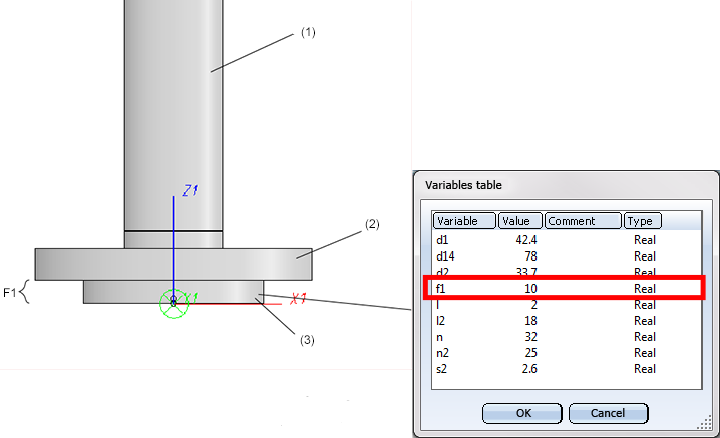
(1) Straight pipe, (2) Loose flange, (3) Collar piece, modelled as straight pipe defining a distance of the loose flange via F1 for the first connecting point.
After insertion of the loose flange, its first connecting point will still be located at the end of the straight pipe, but the part geometry and the second connecting point have been moved away from the connection by the value F1.
 During manual placing of loose flanges, please bear in mind that the Guideline mode must be switched off, and that Connection 1 on target connection must have been selected during insertion.

Rules for the Creation of User-Defined Parts (PE)
|
© Copyright 1994-2018, ISD Software und Systeme GmbH |