When you insert flanges, please note that Connection 1 always refers to the flange connection side while Connection 2 refers to the pipe connection side.
|
When you insert flanges, please note that Connection 1 always refers to the flange connection side while Connection 2 refers to the pipe connection side. |
|

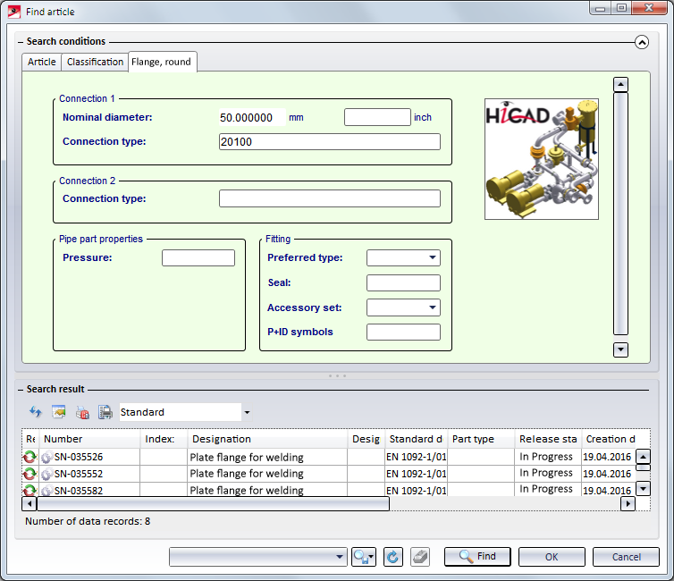
Plant Engineering > New > Pipe parts > Flange 
When you insert a flange, you have the following insertion options.
|
|
|
|
|
|
|
|
Connect flange
When you select the Connect option, (additional) search criteria from the properties of the target part and its selected connection are used (Attributes: NENNWEITE (nominal diameter) and ANSCHLUSSART (connection type). Let us assume that the standard designation of an accessory is contained in the ANSCHLUSSART attribute and it this accessory is a flange, it is added to the search criteria in the NORMBEZEICHNUNG (standard designation) attribute. The insertion direction of the flange depends on the type of target connection, i.e.
If the target object is a flange, and the target connection is on the flange surface, HiCAD inserts an identical flange. HiCAD now displays the crosshairs, thus enabling you to select a new target point for the fitting of the next flange. Search criteria is enhanced by data extracted from the NORMBEZEICHNUNG of the previously inserted flange.
|
|
|
Connect 2 flanges
Select a part with the crosshairs. HiCAD inserts suitable flanges in the appropriate direction in all connections on the part, provided that the connection is located on a guideline and has not yet been joined to the connection of another part. In this case, the same search criteria as those for individual flange insertion apply. |
|
|
Connect all
HiCAD inserts suitable flanges in the vacant flange connections on all guidelines of the active pipeline, provided that the respective connections are located within a guideline, and are not orientated outwards at the end of a guideline, If a guideline end point is located on a flange connection of a part that does not belong to the active pipeline, HiCAD inserts a suitable flange anyway. In this case, the same search criteria as those for individual flange insertion apply. |
|
|
On guideline ends
|
 When connecting one or several flanges, the search criteria for the flange to be fitted always refer to the flange connection to which the flange is to be attached. This means that the nominal diameter assigned to the pipeline or the guideline is always ignored, i.e. even if the Ignore nominal diameter option has not been activated. If the flange connection to which the part is to be fitted belongs to a flange, the same flange is inserted as a counter-flange; this applies even if a pipe class not containing this flange has been assigned to the pipeline.
Plant Engineering > New > Pipe parts > Blank flange 
This function is only available when guideline mode is active, and can be handled almost in the same way as the Connect flange function. Provided that the attribute exists for the target object, DRUCK (pressure) attribute settings are added to search criteria.
A blank flange can also be attached to a flange which is located on the end of a guideline. In this case the blank flange will not be placed on a guideline. The search criteria for the blank flange to be fitted always refer to the flange connection to which the flange is to be attached. This means that the nominal diameter assigned to the pipeline or the guideline is always ignored, i.e. even if the Ignore nominal diameter option has not been activated.
The following parts are available as "loose flanges" in HiCAD:
Loose flanges can not only be placed through an automatism during automatic placing of parts on guidelines, but also be added to a pipeline manually.
Please note the following:
Please note:
Loose flanges can be placed manually or automatically on the connecting point of straight pipes. In the process, the first connecting point of the loose flange will be placed on the connecting point of the straight pipe. Sometimes, however, it is desirable to move the representation of the loose flange slightly away from the connecting point, e.g. in cases where the straight pipe ends with a flanged edge which is not to be overlapped by the geometry of the loose flange. To achieve this, you can define a suitable distance in the feature variables of the straight pipe. For further information, red the information given in the Pipe-dependent placing of loose flanges section.

Pipe Parts (PE) • Part Selection - Catalogue or Database (PE)
|
© Copyright 1994-2018, ISD Software und Systeme GmbH |


