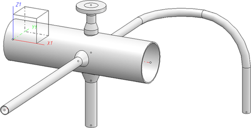
Pipe Parts: Straight Pipes (PE)
Plant Engineering > New > Pipe parts > Straight pipe 
In the selection window, choose the part type Straight pipe from the upper section and the type of insertion from the lower section, where you have the following insertion options:
 Please note:
- A straight pipe that has been modelled as a feature variant cannot be inserted as a "bent pipe".
- If you want to use your own parts or variants of the type "Straight pipe", please read the notes given in the topic Creating New Parts and Variants (PE).
- Multiple branchings can be created, e.g. with saddle connections or straight pipes, originating from one branching point on the centre line of a straight pipe.


In edge direction / In opposite edge direction
Plant Engineering > Pipe parts > Straight pipe > In edge direction / In opposite edge direction  ,
, 
- Select the guideline, on which the part should be inserted, the local coordinate system will be aligned appropriately .
- Select, depending on the current Part selection settings, the desired pipe via part search in HELiOS, or part search in the HiCAD catalogue.
- You can now specify the required fitting length of the pipe.
- Enter 0 if you want to take over the exact length of the selected guideline. In this case, you need not specify a fit-ting point. HiCAD then inserts the pipe with its reference point on the origin of the local coordinate system, and assigns the guideline to Layer 0.If you want to insert the next part, select a guideline, otherwise press the MMB to exit the function.
- If you have entered a fitting length, you need to specify the fitting point on the guideline.
Call the Reference Point menu (right mouse button) and select Connection 1 or 2.
The part is now attached to the cursor. Specify the insertion point on the selected guideline.
HiCAD inserts the part a the specified position on the guideline (c-edge), and automatically divides the edge on the connecting points of the superimposed part. The new edge, hidden by the part, is assigned to Layer 0.
- Answer the query (same part ...) with Yes, if you want to insert further parts on the originally selected guideline, or Cancel to exit the option.
- You can now either select another guideline and insert a part, or press the MMB to exit the function.

Connect part
Plant Engineering > New > Pipe parts > Straight pipe > Connect part 
- Select, depending on the current Part selection settings, the desired pipe via part search in HELiOS, or part search in the HiCAD catalogue.
- You can now specify the insertion length of the pipe. Please do not enter 0. If you want HiCAD to fit the pipe, select the insertion type In edge direction or In opposite edge direction.
- Call the reference point menu (RMB) and select connecting point 1 or 2.
- If you invoke the Select connecting point option, you can use the Autopilot and point option J to snap the connecting point on the start or end of the selected guideline on the connection surface to which you want to attach the part.
HiCAD automatically divides the edge on the connecting points of the superimposed part. The new edge, hidden by the part, is set on Layer 0.
- Answer the query (same part ...) with Yes, if you want to insert further parts on the originally selected guideline, or Cancel to exit the option.
- You can now either select another guideline and insert a part, or select MMB to end the function.
 The Plant Engineering Settings specified on the Part search tab are taken into account for this fitting type.

Set all
Plant Engineering > New > Pipe parts> Straight pipe > Set all 
This option enables you to set a selected part (pipe) on an edge belonging to the composite edge forming the guideline on the active part, whereby HiCAD automatically adjusts the pipe length to fit respective edge lengths.
- Select, depending on the current Part selection settings, the desired pipe via part search in HELiOS, or part search in the HiCAD catalogue.
- All edges that can be inserted in the pipe will now be processed as described under Set individually/Adjust pipe.
Special Cases: Determining Nominal Diameter Values:
If at least one endpoint of a guideline, on which pipes should be automatically inserted, is set on a pipe joint belonging to the same pipeline, HiCAD automatically takes over its nominal diameter. No pipes are inserted if the guideline ends on two joints with different nominal diameters.
Automatic assignment is only possible:
- if no nominal diameter has been assigned to the pipeline and
- if either no nominal diameter has been selected in the pre-selection mask, or has been deselected.


Pipe Parts (PE) • Part Selection - Catalogue or Database (PE) • General Information on Pipe Parts (PE)
|
© Copyright 1994-2018, ISD Software und Systeme GmbH
Version 2302 - HiCAD Plant Engineering
Date: 11/07/2019
|
> Feedback on this topic
|


 Please note:
 ,
, 

 The Plant Engineering Settings specified on the Part search tab are taken into account for this fitting type.
