Settings: Weld Gap (PE)
Plant Engineering > Settings > Plant Engineering Settings > Weld gap
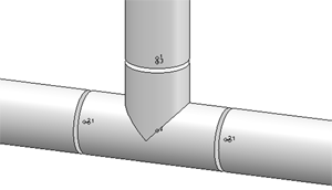
When placing parts on pipelines with the functions Pipe parts and AutoPlace parts on guidelines, you have the option to automatically consider weld gaps. These will be visible as gaps between the parts in the layout plan. In this way the pipe lengths are correctly calculated, i.e. minus the weld gap widths, and output to the Bills of Materials.

If you want to use this option, you need to activate the Consider weld gaps checkbox on the Weld gap tab of the Plant Engineering Settings dialogue, and select the procedure for weld gap calculation:
- via part variant
Weld gaps for various nominal diameters are realised as part variants. These represent no "real" parts, but supply for the corresponding nominal diameter a 3-D part with half of the gap width. Hence, the gap between two butt-welded parts is formed by two of such parts. A weld gap variant called DefaultWeldGap.vaa is supplied with HiCAD. The attribute Standard designation for this variant has been assigned the value ISD_DEFAULT_WELD_GAP. By default, this variant is selected according to this standard designation, and the via part variant option is active.
A weld gap variant can also be assigned to a pipe class. For this the Pipe class also applies to weld gaps checkbox needs to be active. If the Standard designation input field is empty as well (delete content), only the weld gap matching the pipe class of the active pipeline and the corresponding nominal diameter will be used when parts are inserted.
- via direct setting
If this checkbox is active, you can directly set the gap width (in millimetres). For this procedure, too, the part variant with the standard designation ISD_DEFAULT_WELD_GAP will always be used. Instead of the gap width from the VAA file, the directly set value will be used.
Use the Default button to reset the tab to the ISD default settings.
 Please note:
- If you use the HELiOS database as part data source and cannot find the part type Weld gap there, you need to extend the database accordingly.
- If you want to use the option via part variant, you should first derive a new variant from the variant DefaultWeldGap.vaA with the Variant Editor. Enter the desired gap widths, and transfer the variant, via Variant AutoSync, to the part data source (HELiOS database or HiCAD catalogue). Please note that in the variant the variable L denotes one half of the gap width, and variable B the entire gap width. For both variables the matching values need to be entered.


Plant Engineering Settings (PE) • Part Selection - Catalogue or Database (PE)
|
© Copyright 1994-2018, ISD Software und Systeme GmbH
Version 2302 - HiCAD Plant Engineering
Date: 11/07/2019
|
> Feedback on this topic
|


 Please note: