 > Flange connection, bolted
 > Flange connection, bolted

|
|

|
|

|
allow an automatic insertion of an individual bolted flange connection, or flange connections for a complete pipeline.
 The functions are only available if the HELiOS Database has been set as the part data source in the Parts from field, and Standard Part Engineering has been set in the Industry field on the Part selection tab of the Plant Engineering Settings dialogue window
A so-called "bolted flange connection" comprises the complete set of bolts, nuts and washers that are required for the bolting together of two flanges. Seals are not part of the bolted flange connection. The function will not create any bores, because the detailed flange representation already provides them.
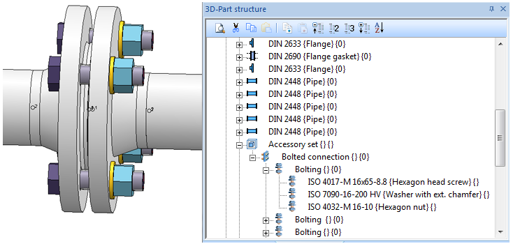
Example:

When you insert a flange connection, a dummy part called Accessory set will be added on the same part structure level in which flanges and the flange seal are located. Below this level, the Bolted connection that represents the bolted connection will be located. In the example above, it consists of four individual boltings composed bolt, nut and washer. The Accessory part is assigned, via external reference, to the flange on which the bolt heads are located (in the example above, this is the left flange). The flange seal, too, is normally assigned to this flange. If you delete this flange, the accessory set part (and with it, also the bolted flange connection) and the flange seal will be deleted.
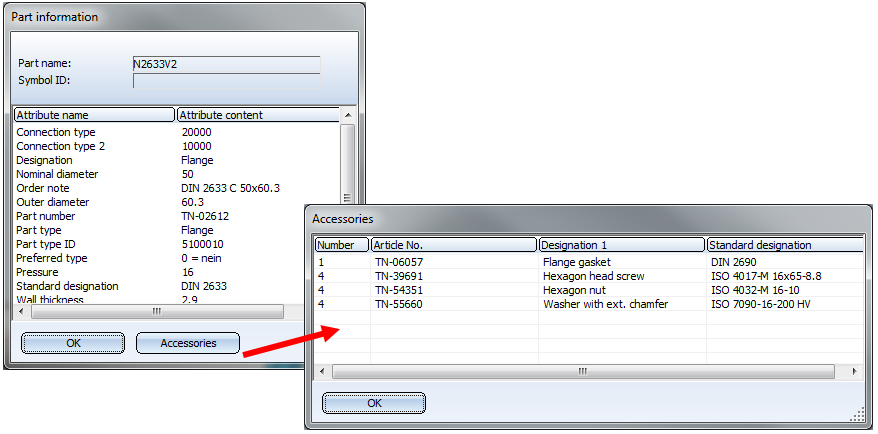
The part information on the left flange (right-click left flange and select Information > Part information) shows that accessory parts exist. Click the Accessories button to view a list of all accessory parts:

In the pipeline isometry these accessory parts are also available for BOM creation.
Prerequisites for the insertion of bolted flange connections
The automatic insertion works for all standard flanges and counterflanges supplied with HiCAD according to
On the Part insertion tab of the Plant Engineering settings dialogue, the option Hollow body, with all details must be activated.
 To delete bolted flange connections, select Plant Engineering > Part Tools > Del.
  > Flange connection, bolted - Delete (Pipeline)
  .
.
 IMPORTANT - Please note the following when working with user-defined variants for flanges or parts with flanges:
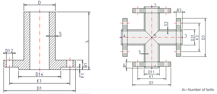
You can use the Flange connection, bolted functions of the Plant Engineering module to place boltings on flange connections. To ensure that the boltings match the flanges, the functions will evaluate the variables of the part variant to which the flange belongs. This also needs to be considered if construct your own parts/variants with flange connections, because otherwise, problems will occur during their processing with the flange connection functions.
The following table shows the lists of variables. The second place of the variable's designation must match the connection number. The list here refers to the example of the first connection of a part.
|
B1 |
Thickness of flange plate (B1 = C1 + F1) |
|
C1 |
Thickness of flange plate (without collar) |
|
F1 |
Thickness of collar |
|
A1 |
Number of bolts |
|
K1 |
Diameter of bore circle |
|
D12 |
Bore diameter |
|
L |
Part length (not connection-specific) |
Hence, the variables of the second connection will have the designations B2, C2, F2, A2, D22.

Additional, part-specific rules apply during evaluation:
The value of the variables NI (capital "N", capital "i", NO "1"!) is used as an additional attribute during creation or querying of an article master in HELiOS. It represents the nominal diameter in Inches.

Part Tools (PE) • Plant Engineering Functions
|
© Copyright 1994-2018, ISD Software und Systeme GmbH |