 > Place cross-sections
3-D FFS > From c-edges > Framew.  > Place cross-sections
Cross-sections can be placed on up to three guidelines. Depending on the number of guidelines, there are different scaling options for the placed cross-section.
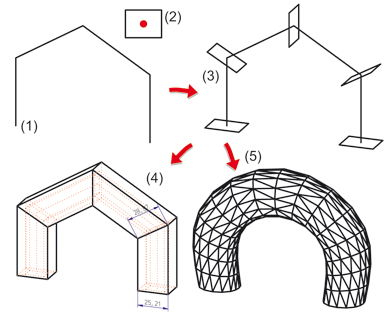
There are two scaling options available for placement on one guideline:
|
Scaling function |
Description |
|
|---|---|---|
|
|
Same profile
|
For polyhedral or freeform surfaces with the same profile, but different cross-section size. For example, the cross-section is enlarged in the area of a mitre. |
|
|
Original size |
For polyhedral or freeform surfaces with the same cross-section size. |

(1) Guideline, (2,3) Cross-section with fitting point, (3) Framework with cross-sections, (4) Polyhedral surface, (5) Freeform surface
Two guidelines are often used for pipe- or container-like forms.
|
|
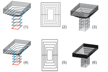
Parallel contour Placing contours parallel to the cross-section. The distance of two contours is the same for this function. |
|
|
Scale Scaling the cross-sections for placement with the scaling factor distance of guidelines : width of cross-section |
|
|
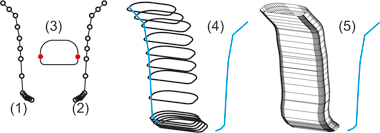
Original size Placement in original size, i.e. the cross-sections placed on the guideline are exactly the same as the identified 2-D cross-section in terms of size and form. The cross-sections are attached to the points of the 1st guideline and placed in the direction of the 2nd guideline. |
When placing a cross-section on two guidelines, you are requested to first identify the two guidelines and the 2-D cross-section. Next, you need to specify two fitting points of the cross-section. The cross-section is placed in such a way that the 1st fitting point lies on the 1st guideline and the 2nd fitting point on the 2nd guideline.

(1) Frame with guidelines and cross-section, scale option:
Parallel contour, (2) Top view, (3) Freeform surface
(4) Frame with guidelines and cross-section, scale option: Scaling, (5)
Top view, (6) Freeform surface

(1, 2) Guideline, (2) Cross-section with fitting points, (4) Frame, scaling option: original size, (5) Freeform surface
![]() Please note:
Please note:
For more complex workpieces, three guidelines are often used. This uniquely defines the plane for the cross-section placement. The three guidelines should be at a right angle to each other when viewed from above, i.e. in such a way that
The division of the guidelines determines the number of cross-sections placed. A fitting point of a cross-section is assigned to each point of the guideline. This means that, for guidelines with a division of 10, the cross-section is placed 11 times, i.e. a cross-section is assigned to each division point of the guideline.
|
|
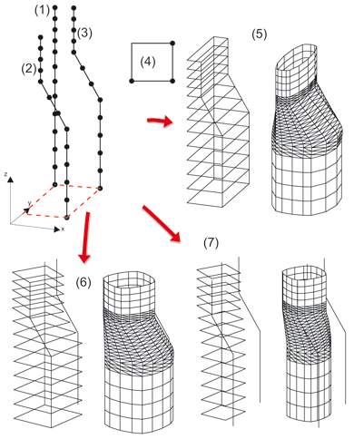
Affinity Setting of affine cross-sections with two different scaling factors. The scaling factors are determined by:
|
|
|
Scale Scaling of placed cross-sections. The scaling factor is determined by the distance between the points of the 1st guideline and the points of the 2nd guideline. The same factor is used to scale the cross-sections from the 1st to the 3rd guideline. The cross-sections created are similar, i.e. the sides of the cross-sections are scaled with the same factor and the angles are preserved. The cross-sections are attached to the points of the first and second guideline and are placed in the direction of the third guideline. |
|
|
Original size Placing of cross-section in original size, i.e. the cross-sections placed on the points of the guidelines are the same as the original cross-section in terms of form and size. As the original size of the cross-section is preserved, the cross-sections here are attached only to the points of the first guideline and placed in the direction of the other two guidelines. |

(1-3) Guidelines, (4) Cross section with fitting points,
(5) Frame + freeform surface, scaling option: affine,
(6) Frame + freeform surface, scaling option: scaling,
(7) Frame + freeform surface, scaling option: original size

Place Cross-Sections (3-D) • Interpolate Cross-Sections (3-D FFS) • Polyhedral Surfaces (3-D FFS) • Overview of Functions (3-D FFS)
|
© Copyright 1994-2018, ISD Software und Systeme GmbH |