 > Scan c-edge
3-D FFS > From c-edges > Framew  > Scan c-edge
You can divide composite edges evenly by scanning reference composite edges. This is relevant, for example, if you are working with two or three guidelines. If the first line has been divided, you can use this function to divide the other two guidelines correspondingly evenly, thus enabling the cross-section to be placed correctly.
Example:
The following figure contains the cross-section of a basin, which is to be placed on the two depicted, closed guidelines. The two 3-D guidelines and the 2-D cross-section have been created as composite edges with the specified dimensions.
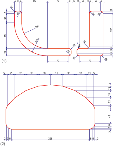
(1) Guidelines, (2) Cross-section
Case 1: Set without scanning
The cross-section is set on the two original guidelines. As the figure shows, the setting is uneven, which is due to the fact that the two guidelines are not evenly divided.
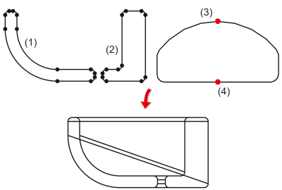
(1,2) Guidelines, (3) Fitting point 1st guideline, (4) Fitting point 2nd guideline
Case 2: Set with scanning
In the 2nd case, a straight, vertical auxiliary edge has been constructed and divided. The Scan c-edge function has then been applied to the first guideline . For this, the following steps were performed once the function was called:
The same process flow was then carried out for the 2nd guideline. The original composite edges of the guidelines can then be deleted.
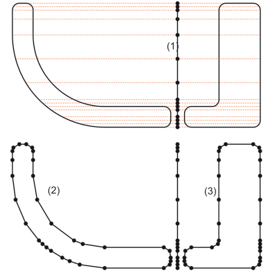
(1) Auxiliary line, (2) New guideline 1, (3) New guideline (2)
If the setting process is now executed using the two new guidelines, it is done evenly.
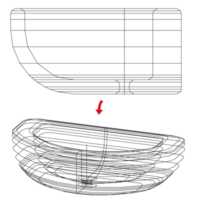
Setting onto new guidelines
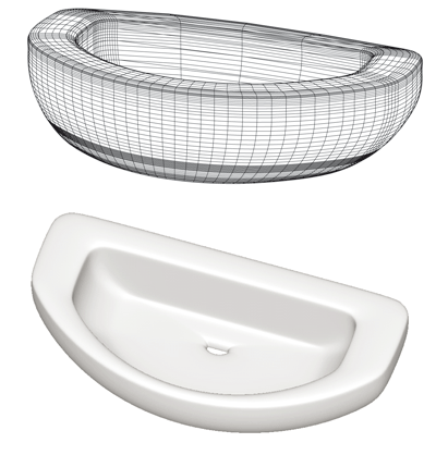
In the following image, a free-form surface has been derived from the created frame.

Process Cross-Sections (3-D) • Interpolate Cross-Sections (3-D FFS) • Polyhedral Surfaces (3-D FFS) • Overview of Functions (3-D FFS)
|
© Copyright 1994-2018, ISD Software und Systeme GmbH |