
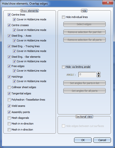
Especially when displaying polyhedrons and freeform surfaces, certain edges that conflict with the rules of technical drawing need to be hidden. Edges are therefore assigned an internal ID, which identifies them as a normal or tangential edge, mesh edge in m-direction, n-direction, mesh diagonal or polyhedral lateral edge. m and n here are the natural parameter directions of a surface, e.g. latitude and longitude of a sphere. Furthermore, edges can also be hidden using the limiting angle or by means of individual identification. The various options are made available in a window. ID, limiting angle and edge identification are treated equally (OR link).
Furthermore, this function enables you to show and hide assembly points, weld seams and processing planes in the active view.
 Clicking
  opens a menu with further edge representation functions:

|
Hidden edges | Defines colour and line type of hidden edges. |

|
Highlighted edges | Highlights edges in colour in glass models or in hidden line representation. |

|
Shading type | Defines the lighting model and the edge shading method. |
The presettings for this dialogue window can be changed in the Configuration Editor, at Drawing > Views > Hiding and overlapping of edges.
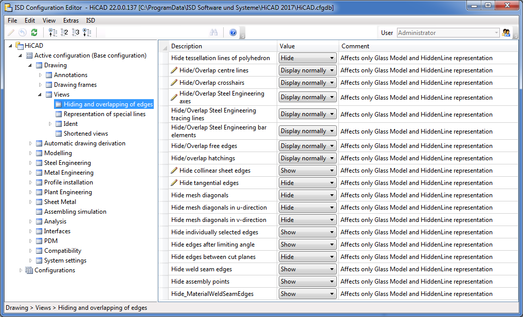

To be able to hide specific edges, you need to know which Edge ID exists or can exist in which part type:
|
Centre lines Centre crosses |
Crosshairs and surface axes of various 3-D elements |
|
Steel Eng. - Axes Steel Eng. - Tracing lines Steel Eng. - Bar elements |
Steel Engineering beams and profiles, Bar elements etc. |
|
Free edges |
Edges that do not attach to a surface and are not part of a composite edge. Free edges can, for example, represent a symmetry axis in solid bodies. Thread edges are handled like free edges. |
|
Hatchings |
If you do not want hatchings to be displayed, deactivate this option. This setting applies to both 3-D surface hatchings and hatchings of sectional views, details and cut-outs. If the option is active, you can hide hatchings that would not normally be visible. Such cases can, for example, occur with sectional views. |
|
Collinear sheet edges |
Developed sheets, flanges etc. |
|
Tangential edges |
Edges the adjacent surfaces of which form an angle of 0 degrees. |
|
Polyhedron - Tessellation lines |
Cylinder, cone (as polyhedron model) Fillets (depending on generation) |
|
Weld seams |
Symbolic weld seam edges (has no effect on weld seams created with HiCAD versions before Version 2017) |
|
Assembly points |
Assemblies (automatically or manually set points)
|
|
Mesh diagonals Mesh in m-direction Mesh in n-direction |
Sphere, Torus: Latitudes (m-direction), longitudes (n-direction) 3-D revolved part, cross-section (n-direction), lines between cross-sections (m-direction) Fillets (depending on generation) |
Examples:
(1) Glass model, (2) Hidden
line with lateral edges, (3) Hidden line without lateral edges
(1) All edges visible, (2) Without mesh edges in v-direction, (3) Without mesh edges in u-direction, (4) 30 degree limiting angle
(1) All edges on, (2) Polyhedral lateral edges off, (3) Tangential edges off
(1) All edges on, (2) Mesh diagonal off, (3) Mesh in v-direction + mesh diagonal off
(1) Cuboid with free edges, centre lines and crosshairs, (2) Free edges + centre line off, (3) Free edges + centre line + crosshairs off
(1) Top view with sketch for the section path, (2) Glass model with hatching, (3) Overlap hatching for a hidden line, (3) Do not overlap hatching for a hidden line
Hide individual edges
Here, you can change the display of individual edges in your drawing. To do this, activate the check box, then click the Select edges button and identify the desired edges in the drawing. Right-click to end the selection and exit the function. The Hide edges, Cover edges dialogue window will then be displayed again.
You should only use this option if the other functions do not produce the required result!
If you choose Remove selection for part list, you undo the changes made to the representation of the identified edges of the active part list or, if no part list is currently active, to the active part; if you choose Remove selection for all parts, you undo the changes to the display of all identified edges.
Hide via limiting angle
You can specify a so-called limiting angle if you want to hide edges between two planar surfaces forming a particular angle. If, for example, you entered a value of 30 degrees, all edges between two flat surfaces (curved surfaces are not taken into account) which form an angle of <30 degrees to one another would be hidden.
You can set limiting angles either for the active part list or, if no part list is active, for the active part, or for all parts of the active view. To do this, click the corresponding button.
![]() Please note:
Please note:
This area of the dialogue window is only active if the active view is a sectional view, a detail view or a cut-out. In these cases you have the option to hide the edges between the cut planes. Activate the appropriate checkbox for this.

View Functions (3-D) • Material and Lighting (3-D)
|
© Copyright 1994-2018, ISD Software und Systeme GmbH |