Variable Through Holes (3-D)
3-D Standard > Standard Processings > Bore.
You do not insert variable through holes via the catalogue system for standard parts and standard processings, but you can insert
them in any sizes by specifying the required dimensions like diameter, bore depth or countersink angle.
The following functions are available in the menu:
 Please
note:
Please
note:
- Once you have called
the function, the Settings dialogue window for bores is displayed (if the Suppress window checkbox has not been activated). Specify the desired settings and choose OK to exit the window. Then define the processing plane, if required.
- The bore can be inserted
individually or multiply on a linear, polar or radial grid. For this, the Grid menu is displayed.
- Before specifying
the fitting position, you can use the right mouse button to activate a context menu. The functions of this menu
enable you to change the fitting direction or the reference point of the
standard part.
- With the exception
of bore patterns, the other functions allow you to fit further copies after inserting a bore.

Through hole
3-D Standard > Standard Processings > Bore
- After having made the corresponding settings, the Through hole dialogue window will be displayed.
- Enter the Diameter of the bore and confirm with OK.
- Choose the desired
fitting type in the Grid toolbar - individual or multiple on a linear, polar or radial grid - ,
and, if required, enter the desired values.
- Specify the fitting
position in the drawing. Position further copies of the bore, if required
and available.
The diameter will be used as the name for the bore in the feature log, e.g. ⌀10.
Blind hole
3-D Standard > Standard Processings > Bore  > Blind hole
- After having made the corresponding settings, the Blind hole dialogue window will be displayed.
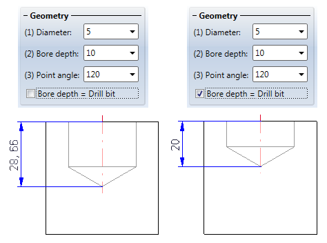
- Enter the Diameter,
the Bore depth and the Point angle. You can influence the Bore depth via the Bore depth = Drill bit checkbox. If the checkbox is activated, the depth of the bore will be the bit of the drill.
- Confirm with OK.
- Choose the desired
insertion type in the Grid
toolbar - individual or multiple on a linear, polar or radial grid - and,
if required, enter the desired values.
- Specify the insertion
position in the drawing. Position further copies of the bore, if required
and available.
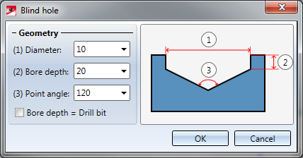
 Blind hole
Blind hole, (1) Diameter, (2) Bore depth, (3) Point
angle
Please note:
- In the Configuration Editor, at System settings > Standard Parts > Required Minimum material thickness for blind holes, you can specify the required minimum material thickness. Values of > 0 stand for the required minimum material thickness. When a blind hole is inserted, a corresponding check will be performed. If you do not want the check to be performed, enter a value of 0 or >0. The default value is 0.01.
- The blind hole will be entered into the feature log with the name Blind hole ⌀d-t , with d being the diameter of the bore and t being the bore depth, e.g. Blind hole ⌀20-10.
Slot
3-D Standard > Standard Processings > Bore > Slot 
- After having made the corresponding settings, the Slot dialogue window will be displayed.
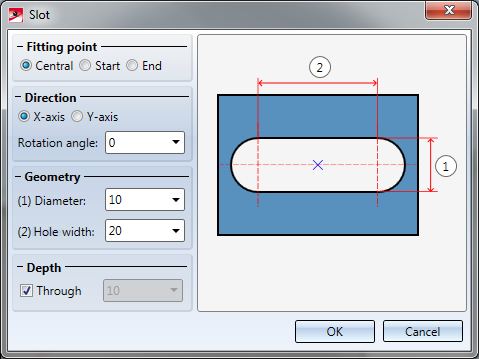
- Specify the Fitting
point: (1) Central, (2) Start or (3) End.
- Choose the Direction of the insertion and enter, if desired, a Rotation angle.
- Enter the Diameter and the Hole width.
- If required,
specify the depth of the bore or activate the Through checkbox.
- Confirm with OK.
- Choose the desired
fitting type in the Grid
toolbar - individual or multiple on a linear, polar or radial grid - and,
if required, enter the desired values.
- Specify the fitting
position in the drawing. The slot is inserted so that this point lies in
the fitting position. Position further copies of the bore, if required
and available.
Slot
(1) - (3) Fitting point options (start, centric, end),
(4) Rotated slot, (5) Slots on a polar grid
The slot will be entered into the feature log with the name Slot ⌀dxl, with d being the diameter of the bore, and l being the witdth of the slot, e.g. Slot ⌀10x20.
Rectangle
3-D Standard > Standard Processings > Bore >Rectangle 
- Enter the Length, Width and, if desired, the Rotation angle. If you want to fillet the corners of the rectangle, also enter the fillet radius.
- If desired, specify the depth of the bore, or activate the Through checkbox. .
- Exit the dialogue window with OK.
- Choose the desired
fitting type in the Grid
toolbar - individual or multiple on a linear, polar or radial grid - and,
if required, enter the desired values.
- Specify the fitting
position in the drawing. Position further copies of the bore, if required
and available.
Punch mark
3-D Standard > Standard Processings > Bore > Punch mark 
Use this function to place individual or multiple
punch marks arranged on a linear or polar grid. Punch marks are used,
for example, to identify subsequent bores.
Before specifying the fitting position, you can use the right mouse button
to activate a context menu. The functions
of this menu enable you to change the fitting direction or the reference
point of the standard part.

Standard Processings
(3-D) • Settings for Bores (3-D) • Repeated Fitting of Standard Parts (3-D)
© Copyright 1994-2018, ISD Software und Systeme GmbH
Version 2302 - HiCAD 3-D
Date: 30/10/2018 |
> Feedback on this topic |