Cross-Section: Move Grid Rectangles (3-D FFS)
Move, grid rectangle
3-D FFS > From c-edges > Framew.  > Grid rectangle
This function enables you to move the points of a grid rectangle in one step.
- Enter the desired
number of points in control line direction and cross-section direction.
The maximum permitted value is the same as the number of points of the
guideline or cross-section.
- HiCAD marks the
grid rectangle defined by the specified number of points, starting with
the first cross-section. By double-clicking the cursor in guideline or
cross-section direction, you can then choose adjacent grid rectangles.
Use END to apply the marked grid rectangle.
- Once you have
applied the desired grid rectangle, define the displacement vector and the value for the displacement. You can then choose whether you want all the points of the grid
rectangle or only its internal points to be moved.
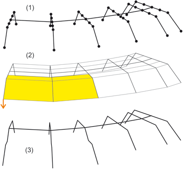
(1) Original frame, (2) Grid rectangles, (3) Modelled frame

Move, rectangle groups
3-D FFS > From c-edges > Framew. > Move, rectangle groups 
This function enables you to select several grid rectangles and their
points in one step.
- Specify the first
rectangle by identifying two frame points.
- Define the other
rectangles.
- Choose END to
end the rectangle selection.
- Specify the displacement
vector.

Process Cross-Sections (3-D) • Interpolate Cross-Sections (3-D FFS) • Polyhedral Surfaces (3-D FFS) • Overview of Functions (3-D FFS)
|
© Copyright 1994-2018, ISD Software und Systeme GmbH
Version 2302 - HiCAD 3-D
Date: 30/10/2018
|
> Feedback on this topic
|