3-D Dimensioning + Text > Parallel
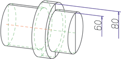
Use the functions in the functions groups Individual dimensions and Parallel to create individual linear dimensions and sets of linear dimensions the dimension lines of which run parallel to one of the axes of the coordinate system, or to a freely selectable reference axis.
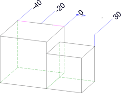
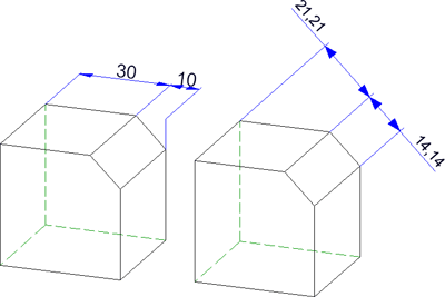
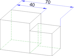
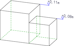
Example: Chain dimension, axially parallel (left) and parallel dimension with chamfer as reference axis
The topics:

The following functions are available:
| 3-D Dimensioning + Text > Parallel | |
|
|
Create new chain dimension Creates a set of dimensions in which two consecutive sub-dimensions have a common dimension point. The dimensions are axially parallel. |
|
|
Create new chain dimension, with reference axis Creates a chain dimension with dimension lines parallel to a selected axis. |
|
|
Create new parallel dimension
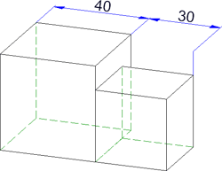
Creates a set of dimensions with all sub-dimensions referring to the same start point and the dimension lines of the sub-dimensions having a fixed distance to each other. The dimensions are axially parallel. |
|
|
Create new parallel dimension, with reference axis Here the dimension runs parallel to a freely definable axis. |
|
|
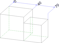
Create new running dimension Creates a chain dimension with all sub-dimensions referring to the same start point (the reference point). The dimension figures will be automatically placed in vertical direction to the dimension line at the end of each sub-dimension. The reference point is indicated by the dimension figure "0". The dimensions are axially parallel. |
|
|
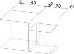
Create new running chain dimension Creates a combination of reference dimension and chain dimension. The dimensions are axially parallel. |

|
Create new running dimension, with reference axis Creates a running dimension the dimension lines of which are parallel to a reference axis. |

|
Create new running chain dimension, with reference axis
Creates a combination of reference dimension and chain dimension. The dimensions are axially parallel to a reference axis. |
|
|
Create new height above datum Special axially parallel running dimension used in Civil Engineering and Steel Engineering. |
|
|
Create new height above datum, parallel to z-axis Height above datum, referring to the XY-plane of the coordinate system Please note:
|
|
|
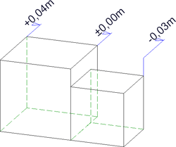
Create new coordinate dimension Special axially parallel reference dimension, in which the first identified point will be interpreted as reference point. From this point, the absolute dimensions between the reference point and the other dimension points will be detected. The reference point will be indicated by the dimension figure "0". |
|
|
Create new height above datum, with reference axis Special running dimension used in Civil Engineering and Steel Engineering, with dimension lines running parallel to a defined axis. |
|
|
Create new coordinate dimension, with reference axis Coordinate dimension, with dimension lines running parallel to a defined reference axis. |
 Please note:
or
Identify the edge to be dimensioned directly and use END (right mouse button) to end the identification.
Please note:
 function or the
  Linear dimension, axially parallel function iin the Individual dimensions menu.
  function in the Individual dimensions menu for creating axially parallel half-section dimensions.
or
Identify the edge to be dimensioned directly and use END (right mouse button) to end the identification.
Please note:
For the creation of individual, linear dimensions running parallel to a reference axis you can also use the Variable dimensions function or the Create new linear dimension, with reference axis  function in the Individual dimensions menu.

Dimensioning (3-D) • Dimensioning - Procedure (3-D) • Linear dimension, free (3-D) • Dimension parameters (3-D)
|
© Copyright 1994-2018, ISD Software und Systeme GmbH |


 >....
>....