 > Directed projection
Sketch > Derive > TakeO... > Directed projection
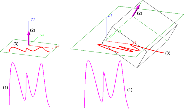
Use this function to generate projections of individual edges, of a composite edge or a line onto a plane. The projection can be performed in any direction and will be assigned to the active sketch.
Activate the sketch onto which you want to project the edges, or create a new sketch.
Call the Directed projection function.
First, specify the direction of the projection:
You have the additional option to right-click and open a context menu with further functions for direction specification.

|
Origin Use this function to make the origin of the active coordinate system the start point of the direction vector. After this you specify the end point. |

|
Z-axis Uses the Z-axis as the direction vector. |

|
Step back Use this function (once or multiple times) to jump one or several steps back in order to correct your input. |

|
Cancel (Esc) Use this function to cancel the direction specification. |
The projection plane is the current sketch plane or processing plane. The angle between the selected direction and this plane must be greater than 0.
The chosen direction vector will be indicated by means of a symbol in the drawing.
In the drawing, select the lines the projection of which you want to apply to the active sketch. The selected lines will be highlighted in the drawing. You have the additional option to right-click and open a context menu with further edge selection options:
|
|
Connected lines or edges* Use this function to take over all edges that are connected to the next identified edge in one step. The lines and edges will be taken over up to a point where a continuation would no longer be unambiguous. This does not apply to the edges of a solid. |
|
|
Tangentially connected lines or edges* Choose this function if you also want to take over all tangentially connected lines or edges when identifying the next line or edge.
|
|
|
Surface boundary * Use this function to take over all edges forming the boundaries of a surface in one step. Select the desired facet with the cursor or select it by identifying two edges. These can also be edges of a solid or of a part with free surfaces. |
|
|
Surface boundary cycle* Use this function to take over a surface boundary cycle, which can be identified by selecting one or two of its edges. These can also be edges of a solid or of a part with free surfaces. |
|
|
Step back If you want to undo one or several steps of the process in order to make corrections, select this option (if required, several times). |
|
|
Cancel (Esc) Use this function to cancel the edge selection. All edges selected up to this point will not be copied into the sketch. |
|
Important note on the selection functions: Normally, already selected lines and edges will be de-selected if you click them again. For the above functions marked with an asterisk *, however, the following applies: If you click lines or edges that have already been selected or if already selected lines are located in a selection, they will not be removed from the selection! |
|
A preview of the projected edges will be shown in the drawing.
To end the function, press the middle mouse button or select Cancel in the context menu.

(1) Original (here: a 3-D sketch); (2) Direction; (3) Projection
 Please note:

Sketch Functions (3-D) • Working with Sketches (3-D)
|
© Copyright 1994-2018, ISD Software und Systeme GmbH |