 Settings
3-D Standard > Standard Processings > Bore >  Settings
Use this function to specify the settings for the insertion of bores.
Geometry and Level of detail
The options in the Geometry and Detailing areas determine the representation of standard processings. You can select whether you want to show them
Bore depth
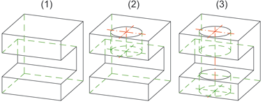
The bore is created, in "bore direction", up to the next surface of the part.
The bore runs through the entire part.

(1) Original part, (2) Bore depth up to next surface, (3) Bore depth, through
Reference plane for bore depth
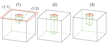
In various cases, such as when fitting a slot in a thread, you can specify a reference plane for the bore depth. You can choose between

(1) Original part with thread runout, bore depth 20, processing plane (1.1) and entry surface (1.2)
(2) Slot fitting, bore depth 30, reference plane = entry surface
(3) (3) Slot fitting, bore depth, reference plane = processing plane
Fitting mode
Here, you specify the plane for bore insertion.
Suppress window
The corresponding setting window is normally displayed each time a fitting function is called. If you do not want this to happen, activate the Suppress window checkbox. If you want to make subsequent changes to the settings, you will need to activate the relevant setting function explicitly.
OK / Cancel
Click OK, to save the current settings as the new default settings. Click Cancel to abort the function without applying the changed settings.
 The Through option cannot be applied to Sheet Metal main parts. When inserting threads across several parts of a Sheet Metal construction, please activate the To next surface option beforehand.

Standard Parts and Standard Processings (3-D)
|
© Copyright 1994-2018, ISD Software und Systeme GmbH |