Feather Keyway (3-D)
3-D Standard > Standard Processings > Thread  > Feather keyways
Use this function to create feather keyways.
- Select the Feather keyways
 function from the Thread pull-down menu.
- The Settings dialogue window is displayed (exception: The Suppress window option is active
in the settings). Make the settings you require
and choose OK to exit the window.
- The catalogue system
for feather keyways will be displayed.
- Select the table you want by clicking the corresponding symbol / list entry, e.g. DIN 6885-1 N1.
- In the right area of the window you can see a list of sizes in which the feather keyway is available. Please note that the width and the height of the feather keyway is always determined based on the diameter of the insertion edge that will be identified later. Therefore, a size selection only influences the length. If you right-click a size, you have the option to pick the shaft diameter from the drawing. In this case, HiCAD will automatically detect the matching height and width of the feather keyway and mark it in the list. You will then immediately see which feather keyway lengths are available.
Click OK to exit the dialogue window.
- Identify the edge for insertion (ellipse or circle).
- For feather keyways for bores (e.g. DIN 6885-1) you can additionally enter a length after identification of the insertion edge. If the automatically displayed length is applied, the feather keyway will be inserted throughout. If the value is changed, the length will be applied starting from the insertion position.
- Specify the insertion position. If the position is to be determined automatically by the already identified edge, click the right mouse button. In this case the keyway will be placed in the centre of the circle (or in the centroid of the ellipse, respectively).
- Enter the rotation angle if you want to rotate the feather keyway about the shaft / bore axis.

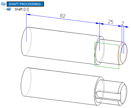
Top: Original shaft with identified insertion edge and processing plane, Bottom: Shaft with inserted feather keyway (DIN 6885 1-N1, 8 x7 x 50), insertion position is the centre of the identified circle.

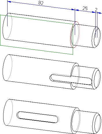
Top: Original shaft with identified insertion edge and processing plane,
Middle: Shaft with inserted feather keyway (DIN 6885 1-N1, 8 x7 x 50). The insertion position was applied with a right-click.
Bottom: Here, the midpoint between the base surface and the top surface of the left cylinder, and a rotation angle of 15° was selected.
 Please note:
- The feather keyway can also be placed at the desired position on the lateral surface of the cylinder by specifying a quad point, or a point relative to a quad point. In such cases you would rotate the feather keyway subsequently by selecting another quad point in the feature log.
- The position of the feather keyway can also be influenced by the use of processing planes. If a processing plane is placed onto the lateral surface before creating the feather keyway, the feather keyway will be created at the position of the plane. By exchanging the processing planes in the feature log, the feather keyway can be rotated subsequently.


Standard Processings (3-D) • Settings for Shaft Processings (3-D) • Shaft Generator (3-D) • Shaft Elements (3-D)
|
© Copyright 1994-2018, ISD Software und Systeme GmbH
Version 2302 - HiCAD 3-D
Date: 30/10/2018
|
> Feedback on this topic
|
 > Feather keyways
 > Feather keyways
 function from the Thread pull-down menu.

 Please note: