Thread Undercut (3-D)
3-D Standard > Standard Processings > Thread  > Thread undercut
Use this function to create thread undercuts.
- Select the Thread undercut
 function from the Thread pull-down menu.
- The Settings dialogue window is displayed (exception: The Suppress window option is active
in the settings). Make the settings you require
and choose OK to exit the window.
- The catalogue system for thread undercuts is displayed.
- Select the table you want by clicking the corresponding symbol / list entry, e.g. DIN 76 A.
- In the right area of the window you can see a list of sizes in which the thread undercut is available. Select the desired size, or right-click to pick the shaft / bore diameter from the drawing. In this case HiCAD will automatically detect the appropriate thread undercut size and mark it in the list.
- Identify a thread facet of the active body.
- Specify the insertion direction. You can right-click to open a context menu, enabling you, amongst other things, to change the insertion direction or the reference point of the thread undercut.

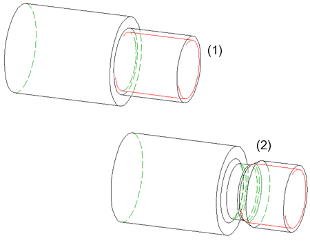
Left: Original part with external thread, Right: Thread undercut; insertion position is the centre of the thread's base surface


Standard Processings (3-D) • Settings for Shaft Processings (3-D) • Shaft Generator (3-D) • Shaft Elements (3-D)
|
© Copyright 1994-2018, ISD Software und Systeme GmbH
Version 2302 - HiCAD 3-D
Date: 30/10/2018
|
> Feedback on this topic
|
 > Thread undercut
 > Thread undercut
 function from the Thread pull-down menu.
