
The Overlap part function enables you to define parts as an overlap contour.
To display the overlap, select Overlap > Visible > Hide hidden edges. You can also define whether you want the hidden lines to be displayed by means of another line type.
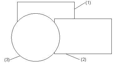
(1) Part 1, level 1
(2) Part 2, level 2
(3) Part 3, level 3

2-D Part > Overlap > Part  > Overlap
contour
> Overlap
contour 
The overlap contour is a prerequisite for representing overlaps. The visualisation level only takes effect when an overlap area has been defined.
You can now specify further contours in any order and define the overlap level.
To display the overlap, activate the Hidden Edges, Hidden function.
2-D Part > Overlap > Part > Exclusion contour 
This function enables you to define the contour for an exclusion, e.g. a bore in a plate, in the active part.
The prerequisites are an overlap contour in the active part and a contour that can be defined as asubtarction.
 from the toolbar to display the exclusion.
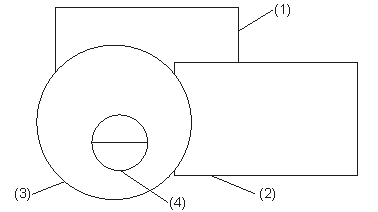
(1) Part 1, level 1
(2) Part 2, level 2
(3) Part 3, level 3
(4) Exclusion contour

Overlap (2-D) • Shift Overlap Level (2-D)
|
© Copyright 1994-2018, ISD Software und Systeme GmbH |