Beam from Sketch (3-D SE)
Steel Engineering > New > Beam from sketch 
This function derives a beam from an arbitrary sketch existing in
the drawing
- Create the corresponding
sketch, if required. When drawing the sketch, note that the distance
of the sketch from the coordinate system is crucial for the subsequent
position of the fitted beam. The beam is fitted at the same distance from
the XY-plane as that between the sketch and the origin of the coordinate
system. The beam axis is always placed in the coordinate origin.
- Once you have
called the Beam from sketch function,
HiCAD first asks you to enter the beam designation. This is used, for
example, in the ICN and in the part list. SKETCH BEAM is proposed as
the default setting. Enter the desired
designation and choose OK to end input.
- Select the material
and choose OK to exit the window.
- Identify the
sketch and specify a 3-D point for the position of the beam axis.
The fitting dialogue window will then be displayed. It is similar to that for the fitting of standard beams. Choose the desired
fitting options, specify
the start point and, if applicable, the end point of the beam.
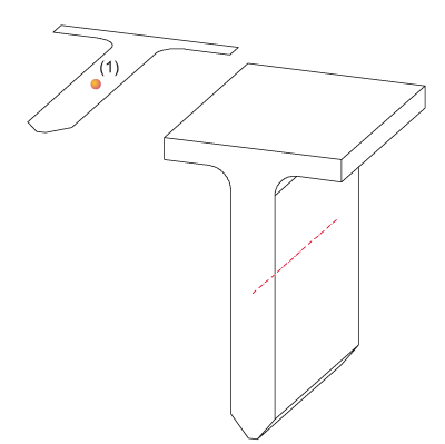
From a sketch (left) derived beam, (1)
Point for beam axis
 Please note:
- You can subsequently change the cross-section of a beam
derived from a sketch using feature
technology. The sketch is entered into the feature log and can be
loaded and processed there.
- The moving of points in a defined rectangle crosswise to the beam axis is also possible for beams derived from sketches (this option is not possible for other beams).

Related
Topics
Fitting
Options for Beams (3-D SE) • Fit Beams
(3-D SE) • Steel Engineering Functions
Version 1702 - HiCAD Steel Engineering | Date: 9/2012 | © Copyright 2012,
ISD Software und Systeme GmbH