 Please note:
 Use the functions in the Text objects group to process the text objects assigned to an isometry and create user-defined text-objects.
 Please note:
 function in the Text function group of the 3-D Dimensioning + Text tab.
![]()
Isometry > Text objects > Create assigned text object 
This function enables you to create a user defined text object, i.e. you can specify its composition. HiCAD assigns a specific ID to this type of object. This means that even when a text object contains connection coordinates matching those of an automatically created text object, it is not recognised by automatic functions. For example, if you invoke the Delete connection coordinates function, the user text object is not deleted.

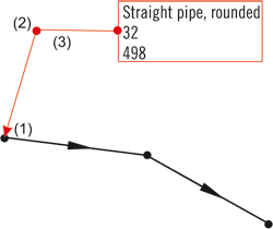
Assigned text object, (1) Start point, (2) angle point, (3) end point
After specifying the part, the Text object dialogue below appears on your screen. The window is handled in the same way as the window for 3-D annotations.
A text object can be composed of
Placeholders for database attributes are in the form %DBA(name), with name representing the name of the database attribute (Example: %DBA(Designation)).
You can specify the entries offered in the selection box in the POSATTR.DAT file in HiCAD’s SYS sub-directory.
Let us assume that an element should contain the attributes %Nennweite1 (nominal diameter1) and %Nennweite2 (nominal diameter2), is structured so that e.g. with the nominal diameter 50 and 32 in text object 50x32 DN appears.
Proceed as follows:
 to transfer the element to the text object.
Detailed information on annotations in the 3-D chapter of the Online Help.
Examples:
|
|
Text object without frame (M), leader line without arrow (L), first element with reactangular frame (K) and leader line connection (H) |
|
|
Text object without frame (M), leader line without arrow (L), leader line connection as in default setting (see Settings - Text/Lines), elements without frames |
|
|
Text object with rectangular frame (M), leader line with arrow (L), leader line connection as in default setting (see Setting - Text/Lines), elements without frames |
|
|
Text object with rectangular double frame (M), without leader line (L), elements without frames |

|
Text object on lengthened tag (M), leader line without arrow (L), element without frame (K) and leader line connection (H) |
|
|
Text object without frame (M), without leader line (L), elements without frame (K), Elements in one row (N) |
Select Apply to take over the current mask settings. Select Cancel to end the Annotation settings mask without applying the current settings.
 Annotating connection points of a pipeline:
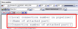
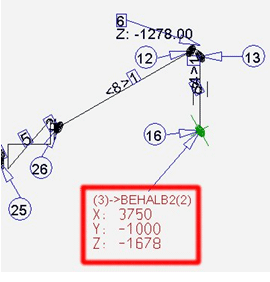
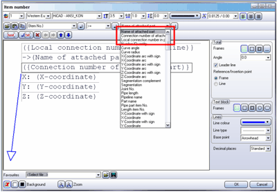
When annotating coordinate points on pipelines you can also add information on inserted components:


The example shows a very simple formatting, without frame or similar; the formatting can be specified further by the user. The local connection number is part of a consecutive numbering of all open end points of the pipeline and is not to be confused with the connection number.

In the case of connected pipelines in other isometries, this consecutive number is used as a "remote connection number". For vessels, the number of the respective connection point is used.
![]()
Isometry > Text objects > Edit assigned text object 
If no pipeline is active, use the graphic cursor to identify a part in the pipeline you want to process. When HiCAD asks for confirmation, respond with Yes.
Identify the text object with the cursor.
You will get the same dialogue box as for the Create assigned text object function; here, however, you are enabled to process all text objects, i.e. not only the user-defined ones. With this function, you do not create a new text object, but change an existing one.
Select Cancel to end the dialogue box without applying the changes. Select Insert to end the dialogue box and take over the changes.
![]()
Isometry > Text objects > Move assigned text object 
If no pipeline is active, use the graphic cursor to identify a part in the pipeline you want to process. When HiCAD asks for confirmation, respond with Yes.
Identify the text object with the cursor. You can specify an angle point with the right mouse button, the endpoint with the left mouse button and the position of the text object. The leader line only appears if the appropriate option has been preset.
![]()
Delete assigned text object 
If no pipeline is active, use the graphic cursor to identify a part in the pipeline you want to process. When HiCAD asks for confirmation, respond with Yes.
When you identify the required text object with the cursor HiCAD immediately deletes it.
This function is only available in the context menu of the isometry (right-click on a part in the isometric drawing)!
Related Topics
Isometry (Iso) • Isometry functions for the layout plan (Iso) • Plant Engineering Functions
Version 1702 - HiCAD Plant Engineering | Date: 9/2012 | © Copyright 2012, ISD Software und Systeme GmbH