Variant for Part Type: Welding Neck
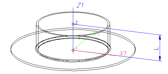
Named isolated points
|
Designation |
Purpose |
Comment |
Position in coordinate system |
|---|---|---|---|
|
! |
Connecting point |
Fitting point |
in origin (0,0,0) |
|
2 |
Connecting point |
|
X = 0, Y = 0, Z > 0 |
|
Name |
Description |
Attribute (optional) |
|---|---|---|
|
L |
Distance between point “!“ and “2“ |
LAENGE |
If the variables names given in the Name column are used, you do not need to assign any attributes to them via the Variant Editor. If different variables are required, you need to assign the attributes given in the Attribute column.
VAA file
Use the Variant Editor to enter the suitable part type into the VAA file.
Then, use the Variant Editor to expand the VAA file in such a way that it contains values for the sizes specified here, and that the predefined attribute assignment is entered:
|
Parameter All dimensions must be specified in millimetres; |
Variable (suggestion) |
Assigned attribute |
|---|---|---|
|
Nominal diameter, Connection “!“ and “2“ |
N |
NENNWEITE |
|
|
||
|
Additionally (only if the corresponding standard uses nominal diameters in inches): |
||
|
Nominal diameter (inches), Connection “!“ and “2 |
NI |
N_INCH |
|
Nominal diameters in inches need to be entered as decimal values as well (e.g. 1.5 for 1 1/2‘‘). |
||
|
|
||
|
For a connection socket, these sizes refer to the pipe to be plugged in: |
||
|
Outer diameter, Connection “2“ |
D |
D_AUSSEN |
|
Wall thickness, Connection “2“ |
F1 |
WANDDICKE |
If required, the attribute LAENGE (LENGTH) needs to be assigned to the length variables (see Variables names above).
For variant synchronisation, values must still be entered for the attributes that are to apply equally to all sub-types of the variant.
Values must be entered for at least the following attributes:
|
Attribute |
Description |
|||||||||||||||||||||||
|---|---|---|---|---|---|---|---|---|---|---|---|---|---|---|---|---|---|---|---|---|---|---|---|---|
|
BENENNUNG |
Designation of part |
|||||||||||||||||||||||
|
COMPONENT_TYPE |
Part type (always = Semi-finished material + Plant Engineering) for HELiOS database only |
|||||||||||||||||||||||
|
NORMBEZEICHNUNG |
Standard designation of the part (identical for all sub-types!) An entry is mandatory, even if the part corresponds to no standard. |
|||||||||||||||||||||||
|
BESTELLVERMERK |
Order note, individual content |
|||||||||||||||||||||||
|
|
|
|||||||||||||||||||||||
|
ANSCHLUSSART |
Connection type for Connection “!“ (always flange connection) |
|||||||||||||||||||||||
|
ANSCHLUSSART2 |
Connection type for Connection “2“ |
|||||||||||||||||||||||
|
Possible values of the attribute ANSCHLUSSART (CONNECTION_TYPE)
The last character (x) provides information about the meaning of the supplement: 0 =No supplement 2 = The supplement consists of connection number, part type, ID, and standard of the part to be connected The prefixed connection number indicates the connection with which the auxiliary part is to be attached to the current connection.
|
||||||||||||||||||||||||
If welding necks are to be inserted with the loose flange from the connection attributes, the AutoFit connecting parts option must be activated on the Part selection tab of the Plant Engineering Settings dialogue window.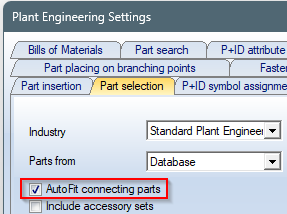
 Handling of nominal diameters in inch in the HELiOS database:
During part data sync, the nominal diameters in inch are transferred as decimal numbers to the attributes N_INCH, N2_INCH and N3_INCH. The usual character strings for specifying the nominal diameters in inch (e.g. 1 1/2'' instead of 1.5) are automatically generated in the database for the attributes NPS_INCH, NPS2_INCH and NPS3_INCH..

