Example: Variant of a Planar Infill
In this example a planar infill, consisting of a plate, 2 welded holders on the right ans 2 on the left are to be created as railing variants.
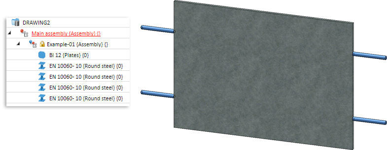
Planar infills require at least the variables i_l and i_h.
- i_h
Distance between floor and handrail. - i_l
Distance between 2 posts.
In this example, only the these two mandatory variables will be of relevance, i.e. this component can only be used for planar infills (an example for railings with rise can be found in the Example variants).
Step 1: Create and parameterize the plate
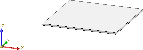
The steel plate used in our example must be derived from a sketch.
- Activate the top view and draw a sketch (Sketch > New > Create new sketch in plane, as main part
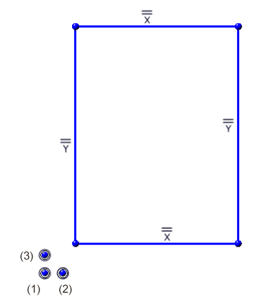
 ). First, define 3 isolated points (Sketch > New > New point
  ) as an aid for the later parameterization, with the following coordinates:
- Absolute (0,0,0)
- Absolute (100,0,0) and
- Absolute (0,100,0).
- Switch the automatic positional constraints on (Sketch > HCM > Tools
 > Settings
  > Automatic HCM settings: Create and draw a rectangle as shown below (Sketch > Draw > Draw rectangle
  ):
):
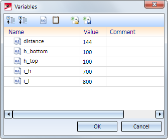
- Now parameterize the sketch. In this example, the plate does not cover the entire space between the posts and the floor / handrail, so that the holders must be taken into account here. Also, we want the distance of the plate to the floor and to the handrail to be flexible. Therefore, we want to use the following variables here:
| Variable | for | Start value |
|---|---|---|
| i_h | Distance between floor and handrail | 700 |
| i_l | Distance between 2 posts | 800 |
| distance | Width of holders | 144 |
| h_top | Distance to handrail | 100 |
| h_bottom | Distance to floor | 100 |
|
h_holder |
Distance of holder from upper and lower edge of plate |
100 |
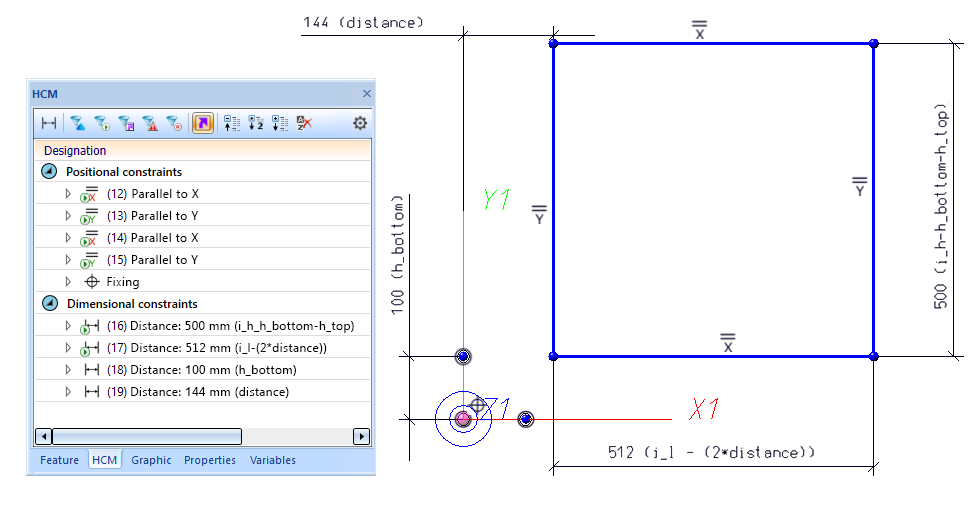
For the width and height of the plate this means:
- Plate width= i_l - (2*distance)
- Plate height = i_h-h_top-h_bottom
First, fix the isolated point (1) (Sketch > HCM > Fix geometry  ). This point represents the origin. Then, assign the variable to the sketch by defining the corresponding HCM dimensional constraints (Sketch > HCM > Smart dimensioning
  ):
):
|
Dimensional constraint for |
Variable |
Start value |
|---|---|---|
|
Distance of left edge of sketch to point (1) |
distance |
144 |
|
Distance of lower plate of sketch to point (1) |
h_bottom |
100 |
|
Width of sketch |
i_l - (2*distance) |
800 for i_l |
|
Height of sketch |
i_h - h_bottom- h_top |
700 for i_h 100 for h_top |
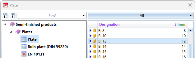
- Now, convert the sketch to a steel plate (Steel Engineering > Plate, new > Plate from sketch
 ) and choose Delete sketch when exiting? Yes. In both cases, choose the origin (RMB) as insertion point and fitting point.
Step 2: Assembly and Fitting CS
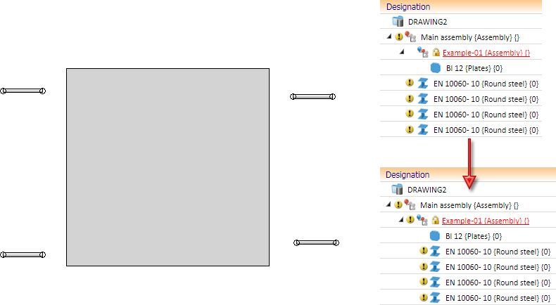
- Create a new assembly (3-D Standard > New > Assembly
 ) and move the previously created plate into the assembly in the ICN via Drag & Drop.
 -
Not all assembly automatically have a Feature log. If you assign a Fitting CS to these assemblies, no corresponding Feature entry will be created. However, such an entry is mandatory for the variants. Therefore, assign a body creation feature to the assembly. To do this, right-click in the Feature window of the assembly and choose Activate.
Furthermore, the function must use external references. To do this, activate the Use external references option in the upper part of the feature log.
- The variables are currently assigned to the plate. Therefore, activate the plate, right-click and choose Part variables. Mark all variables, right-click them and choose Cut. Then, activate the assembly, call the Part variables function again and click
 to paste the variables here. The variables have now been assigned to the assembly.
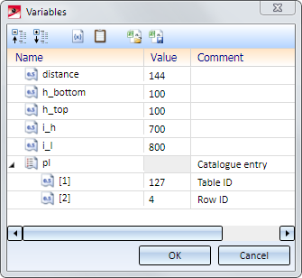
- When you derived the steel plate you chose a particular plate from the semi-finished products catalogue. But when choosing the railing component in the Railing Configurator, the plate should not be an invariable, fixed plate, but a plate that can be freely selected from particular tables. You therefore need the variable pl of the type List for the semi-finished product. Right-click on the variable entry pl and select the option Add new variable. For Type, select Number and enter 127 for Value. Then create another entry for the variable pl of type number with the value 4.
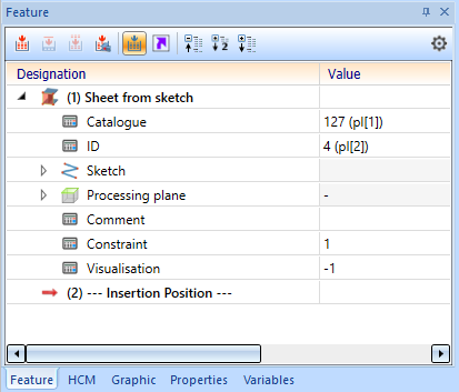
The variables pl[1] and pl[2] are then assigned to the feature of the plate. To do this, first right-click on the Catalogue entry and then select Edit formula. In the corresponding dialogue window, enter pl[1] and repeat the process for the entry ID and the variable pl[2]:
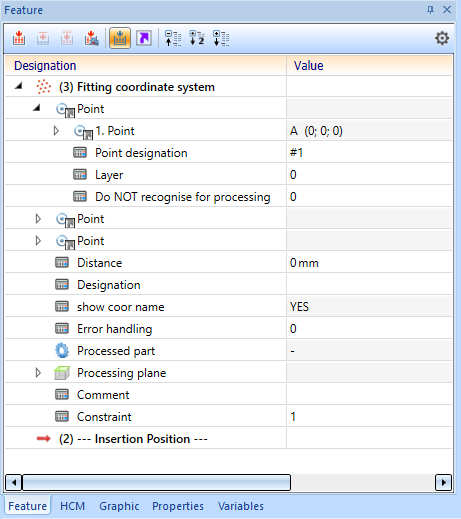
- Now, define the Fitting CS with the function Drawing > Others > World CS > Define Fitting CS
 as follows (the assembly must be active!):
 - New origin of CS in Absolute (0,0,0)
- Point on X-axis: in Absolute (100,0,0) and
- Point on Y-axis in Absolute (0,100,0).
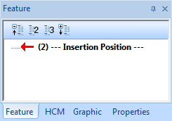
The Fitting CS will then be entered into the Feature log of the assembly (the points coincide with the isolated points you used when you created the sketch).
Step 3: Insert holders and parameterize:
- Now insert the holders. To do this, switch to the top view and insert 4 holders of the type Round steel DIN EN 10060-10, while using the insertion settings shown below. Use the Steel Engineering > New > Beam > Bar element
 function to do this, and the length is not important here at the moment. Then assign the holders to the assembly using drag & drop in the ICN.

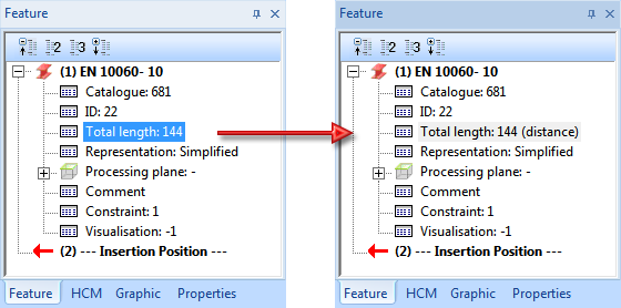
- The width of the holders should be the same as the distance between posts and plate (distance variable). Therefore, change the total length in the Feature log of the holders, and enter the variable distance for Total length > Length via the function Edit formula. This step must be applied to all 4 holders.
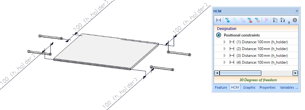
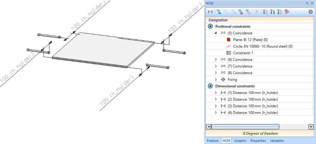
- The holders must have a certain, variable distance from the upper / lower side of the plate. To achieve this, assign suitable distance constraints (3-D Standard > HCM > Distance between 2 parts
 ) between the axis end point of each holder and the upper / lower side of the sheet. For this you use the variable h_holder. This step , too, must be applied to all 4 holders, and the assembly msut be active. The HCM model will then obtain 4 distance constraints.
- Fix the plate with the function 3-D Standard > HCM > Fix sub-part
 .
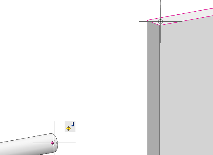
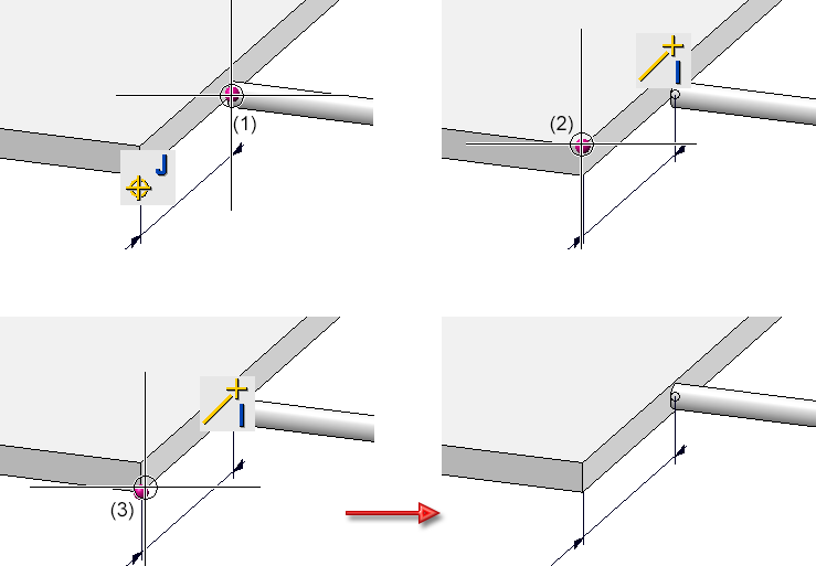
. - The holders should border exactly on the lateral sides of the plate. You achieve this by assigning coincidence constraints (3-D Standard > HCM > Coincidence
 ) - in all of the 4 cases between the lateral side of the plate and the base surface of the corresponding round steel. Here, too, the assembly must be active in the process.
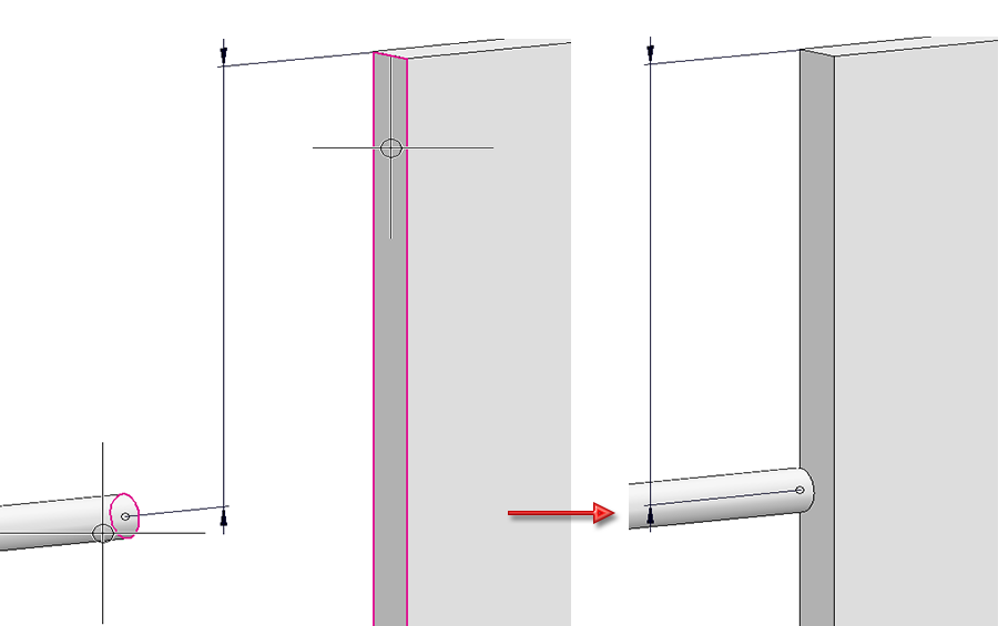
- Also, the holders must be aligned vertical and centred on the lateral sides of the plate. That is, you will need an additional HCM constraint for each of the holders. Here, a coincidence constraint of the type Mid-point (3-D Standard > HCM > Coinc... > Mid-point
 ) is required, namely, between the end point of the holder axis and the start/end points of the plate edges.
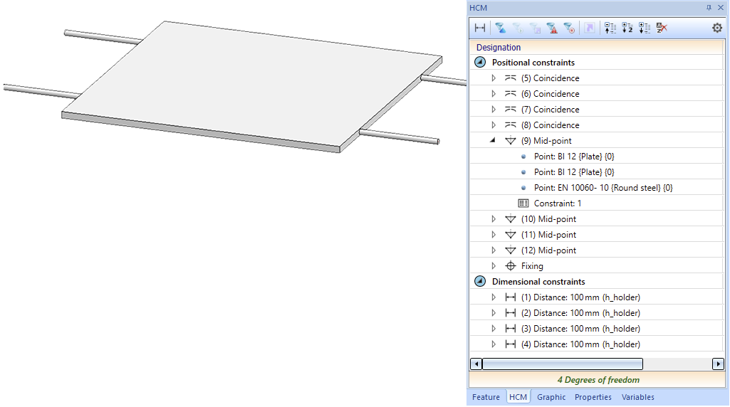
You are now done assigning all required variables and HCM constraints to the assembly.
- Now, change the part name (in the ICN Properties and the Article number (Part attributes) of the assembly to Example_Infill.
Step 4: Save assembly as variant
To save the assembly as a variant, select the assembly and, in the Civil Engineering functions docking window, choose Steel Engineering > Stairs + Railings > Railing > Variant Editor for railings.
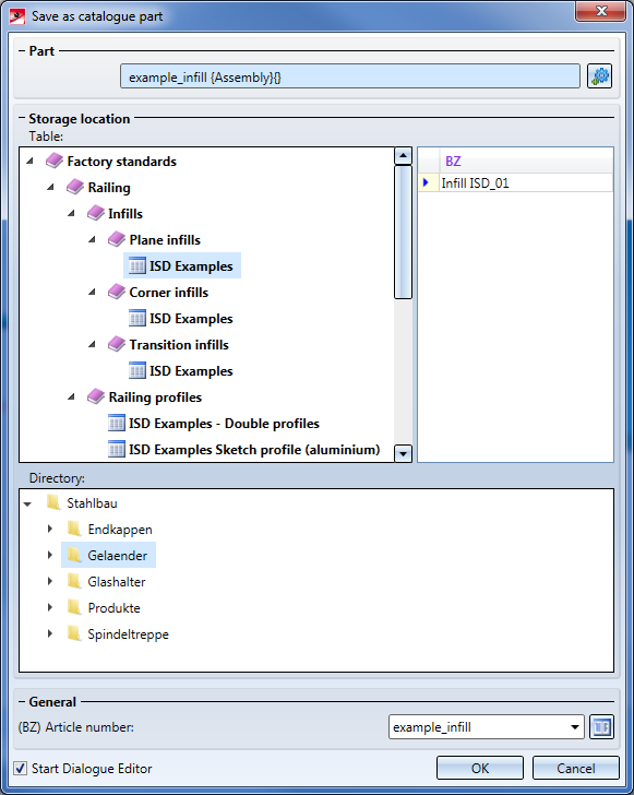
To create our customized dialogue, activate the Start Dialogue Editor checkbox and confirm with OK.
In the HiCAD folder Kataloge\Werksnormen\Stahlbau\Gelaender\EbeneFuellung the following files will be created:
- Example_Infill.CSV and
- Example_Infill.KRA
The HiCAD Dialogue Editor will be started automatically and the CSV files will be loaded. The customized dialogue can now be created.
How to Create Customized Dialogues


Variant Editor for Railings • Stairs and Railings (3-D SE) • Steel Engineering Functions