Edit Import Settings
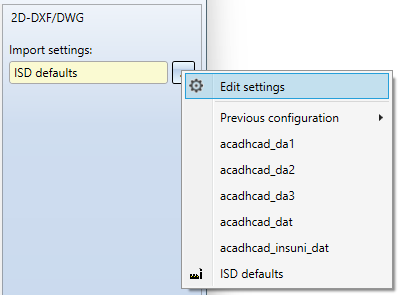
Im import dialogue for 2-D DX/DWG files you can call up an extended dialogue window for the export configuration via Import settings > ... > Edit settings to open an extended dialogue window for the import configuration.
The Import settings 2-D DXF/DWG dialogue window consists of the following tabs:

General
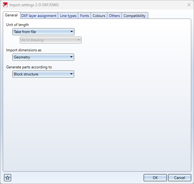
| Unit of length |
For the import, you can select the Unit of length in which the data of the DXF file are to be interpreted. Usually the header variable $INSUNITS of the DXF file is evaluated via the setting Take from file, the data is interpreted according to this header variable and converted into the current HiCAD drawing unit.
Also, you can select Given e in order to select another unit of length in which the data are to be interpreted in the then active pull-down menu below.
In addition to the Millimetres, Centimetres, Decimetres, Metres, Inches and Feet that can be set as import units, you can activate the As in drawing option. However, the HiCAD drawing unit does not change when importing a DXF file depending on the unit of the DXF file. It remains the same, or corresponds to the unit for a new HiCAD drawing when a new drawing is created. |
| Import dimensions as |
Here you can select whether the dimensions of the DXF file are to be generated as 2-D Dimensions or as Geometry. However, real dimensions are generated only if the DXF file already contains dimension objects (DIMENSION). By default, no real dimensions are created, which is why the default setting is Geometry.
If the header variable $INSUNITS of the DXF file is to be interpreted (settingUnit of length = Take from file) and the header variable $INSUNITS of the DXF file contains a unit other than mm, the generation of "real" dimensions may be faulty. |
| Generate parts according to |
This option allows you to select in which structure the geometries and texts of the DXF file are transferred to HiCAD: Block structure or Layer structure. By default, the parts are transferred to HiCAD using the DXF Block structure. If Layer structure is set, a separate 2-D part is created for each layer from the "LAYER" table of the DXF file, to which all geometries and texts of the DXF file with corresponding layer are transferred. (This option replaces as of HiCAD 2023 Service Pack 1 the former keyword setting option "LAYFI" in the corresponding configuration file). |
 In earlier HiCAD versions the $INSUNITS variable was not evaluated and the data was not scaled accordingly. If the $INSUNITS variable is set in the DXF file, the data is now scaled (if it is in a unit other than mm).
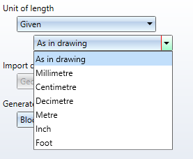
DXF layer assignment
On this tab of the import settings you will find options for assigning DXF layers to HiCAD layers:

Via the table in this tab, the DXF layers can be assigned to a HiCAD layer in the columns DXF layer name and HiCAD layer according to their layer name in the DXF file.
Here, for example, the DXF layer with the layer name "TEXTLAYER" is assigned to the HiCAD layer "48". This option has priority over the numerical assignment.
Further assignments can be added via  : A new row will be added in which you can make corresponding entries.
|
Assign DXF layers numerically |
This option, activated by default, can be used to control whether DXF layers with a numerical layer name are transferred to the HiCAD layer with the corresponding number. This does not apply to DXF layers with names "0". |
|
Take over DX layer names |
By default, the layer names of DFX files are not transferred as HiCAD layer names. If this option is activated, then the layer names of DXF layers are transferred as HiCAD layer names during import. This setting should only be used if the layer names are also required in HiCAD. |
(These options replace the former keyword settings "LAYNR" and "LAYNA" as of HiCAD 2023 Service Pack 1, and the former keyword setting "LAYER" in the corresponding configuration file as of HiCAD 2024).
Line types
On this tab, DXF line types are assigned to certain HiCAD line types and a HiCAD colour on the basis of their designation.
The HiCAD colour is optional and can be set if the checkbox is activated.
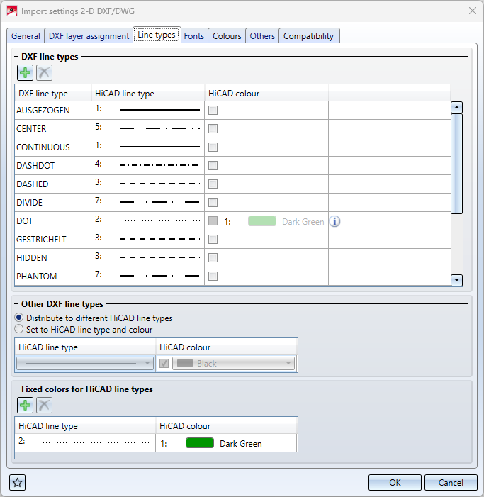
Below this, you can select via Other DXF line types whether DXF line types not assigned above are to be distributed to different line types or whether all unassigned DXF line types are to be transferred to a fixed HiCAD line type. Optionally also with fixed HiCAD colour.
Via Fixed colours for HiCAD line types, fixed HiCAD colours can be assigned to respective HiCAD line types. It is then no longer possible to select the colour for these line types in the upper table.
(This options dialogue replaces the configuration file keywords "LTYPE", "LTYPE *" and "COLAR" of earlier HiCAD versions).
Fonts
With the help of the configuration table under DXF style on the Fonts tab, DXF font names can be assigned to corresponding HiCAD fonts.
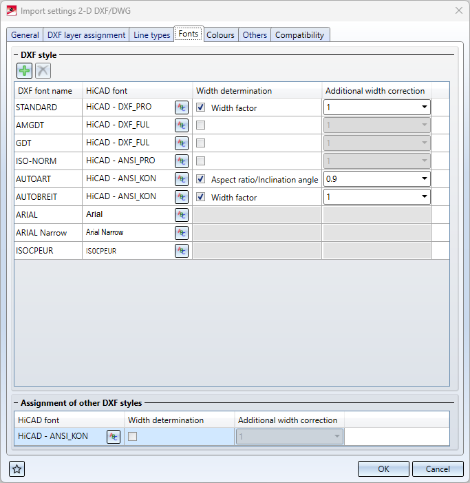
 HiCAD fonts can be the special HiCAD fonts as well as the installed Windows fonts.
For HiCAD fonts, the type of Width determination can also be selected:
-
If Width factor has been selected, the width factor of the text is determined by the width factor of the DXF text in the DXF file.
See e.g. 2-D Dimensioning+Text > Text > New >

-
If Aspect ratio/Inclination/Inclination angle has been selected, the aspect ratio and inclination angle are determined from the width factor and the inclination angle of the DXF text in the DXF file..
See e,g, 2-D Dimensioning+Text > Text > New >

In addition, in both cases a factor for width correction can be set in the column Additional width correction.
If no checkbox is activated here, the button next to the HiCAD font  can be used to set the Aspect ratio and Inclination via a pull-down menu of the Font > HiCAD font window.
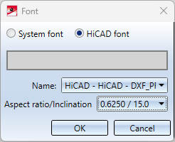
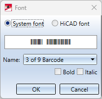
Via this dialogue window it is also possible to choose between System fonts and HiCAD fonts.
For Windows fonts (System fonts) it is not possible to determine the width. For these fonts, however, the properties Bold and/or Italic can also be selected here:
Via Assignment of other DXF styles, at the bottom of the dialogue window, a HiCAD font can be assigned for all DXF fonts that are not explicitly listed in the table above.
(These options replace the configuration file keyword "STYLE" of earlier HiCAD versions).
Colours
The DXF colour index can be assigned to a corresponding HiCAD colour via the upper colour table DXF colours.
By default, 9 DXF/HiCAD colour assignments are predefined.
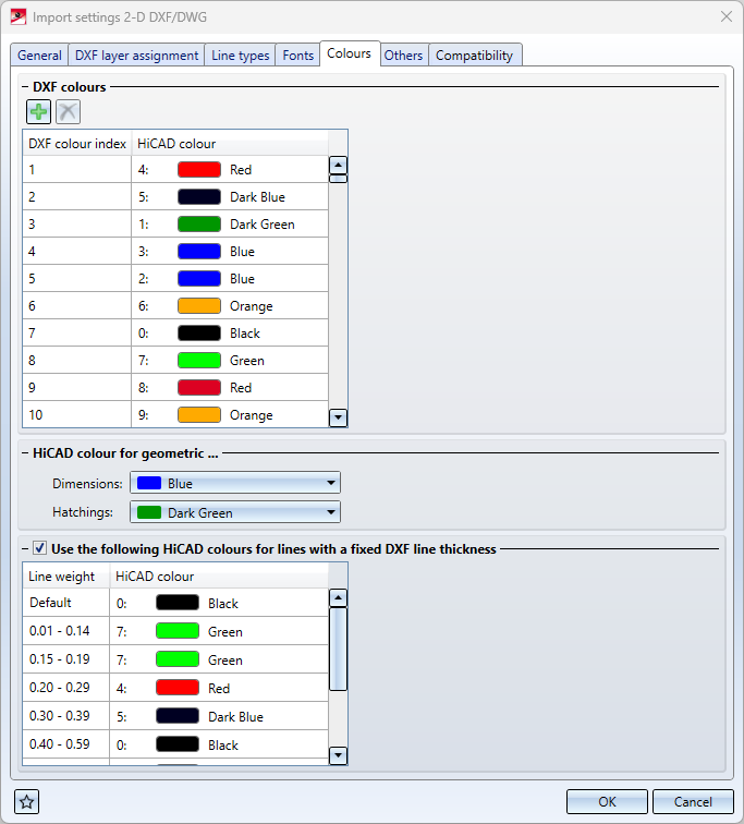
Non-defined colours are assigned the system colour 0 in HiCAD.
In the dialogue window, new rows can be added by clicking on , or rows can be deleted by selecting them and clicking on  .
.
Under HiCAD colour for geometric... you can also specify the following:
-
Dimensions: Here you can select the colour in which dimensions are generated during import. The selection of the colour for dimensions is limited to geometric dimensions. By default, geometric dimensions are generated in HiCAD system colour 3 (blue).
-
Hatchings: This "option" allows you to select the colour in which hatchings are generated during import. The selection of the colour for hatchings is limited to geometric hatchings. By default, geometric hatchings are generated in HiCAD system colour 1 (dark green).
Important: This option only affects "Block" hatchings, not "HATCH" hatchings.
(As of HiCAD 2023 SP 1, these options replace the former setting options "COLOR" and "COLBE" in the corresponding configuration file).
In the lower half of the window you will find another assignment table under Use the following HiCAD colours for lines with fixed DXF line thickness, which you can deactivate/activate via checkbox.
Here, lines can be assigned to a certain HiCAD colour depending on their DXF line thickness.
The assignments only take effect if the group code 370 is set in the DXF file. The default in the DXF file corresponds to the values "-1(bylayer)", "-2(byblock)" and "-3(default)".
If the checkbox is not active, these line thicknesses are not taken into account.
(This option replaces the configuration file keyword "COLWE" of earlier HiCAD versions).
Others
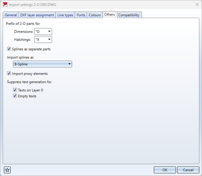
| Prefix of 2-D parts for |
These menu items can be used to define prefixes, which serve as block identifiers for Dimensions and Hatchings. By default, the Dimension prefix is "*D" and the Hatchings prefix is "*X". (These options replace the previous code setting options "BLKBE" and "BLKSR" as of HiCAD 2023 Service Pack 1). |
| Splines as separate parts |
This option can be used to determine whether splines should be transferred to separate 2-D parts. By default, splines are transferred to separate 2-D parts. (This option replaces the former code setting option "SPFIG"). |
|
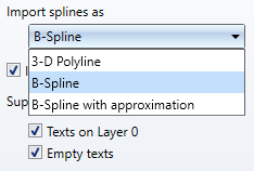
Import splines as |
Via the pull-down selection, splines from 2-D DXF files can be imported into HiCAD as 3-D polyline, B-spline or B-spline with approximation.
((This option replaces the configuration file keyword "SPLIN" of earlier HiCAD versions.) |
| Import proxy elements |
This option can be used to determine whether PROXY elements of the DXF file should be transferred. DXF/DWG files can contain PROXY elements, in which a large part of the geometry can be located. These elements are generated by AutoCAD add-on programs and can only be represented exactly with them. However, a proxy graphic is usually entered in the DWG/DXF file. With this option these proxy graphics can be transferred to HiCAD. By default, the option is active. (This option replaces the former code setting option "PROXY"). |
|
Suppress text generation for |
Texts on Layer 0: With this option it can be suppressed that texts are generated which are on DXF Layer 0. By default, texts on Layer 0 are not transmitted. (This option replaces the former code setting option "TSCH0").
Empty texts With this option the generation of empty texts can be suppressed. By default, empty texts are not generated. (This option replaces the previous code setting "TLEER "). |
Compatibility
On the Compatibility tab you will see a list of all other configuration codes that have been set, their respective Values and a Comment line for them.
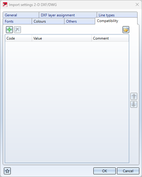
Here you have the possibility to change settings based on configuration files that are not shown in the import settings interface.
You can change a Value by clicking in the corresponding field and changing it manually.
You can edit an entire row including Code and Comment by selecting it and clicking on the symbol in the upper left corner.
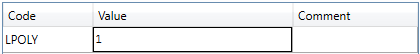
An example: Create the Code with the value "1" if all layouts and the model as well as the option 'all' are to be offered when reading in the 2-D DXF/DWG file. (Note the selection of individual layouts always deletes the model).
The default value for LPOLY in the ISD default settings is "0" (i.e. all layouts incl. model are read in at once without query).
You can load the configurations from older configuration files (e.g. an old ACADHCAD.DAT) by clicking on the  symbol at the bottom of the window and selecting a corresponding one in the following selection dialogue. If the file has been successfully transferred, you will receive a system message.
Clicking the  symbol at the bottom left opens the Favorites menu.
