Part Structure Representation in the ICN

General information
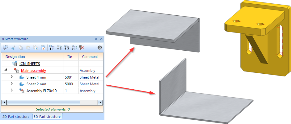
The middle window of the ICN displays the part structure of the active drawing – separately for 2-D and 3-D parts. It provides you with information on the assemblies, main parts and sub-parts, part types etc. that exist in the current drawing. The first entry in the part structure is always the name of the current drawing. If you right-click this name, the context menu for drawings is displayed.
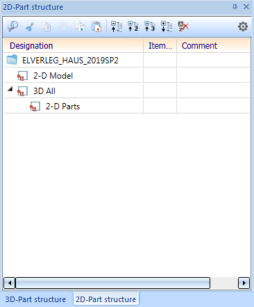
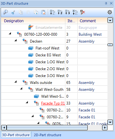
The display is in a tree-like structure, as is standard in Windows, starting from the name of the drawing file. For each part, a graphic symbol for the accordting part type and the article number or rather the part type if the article number is not assigned yet. Furthermore, further attributes are represented in the 3-D Part structure. The item numbers and the part type are shown by default
In order to browse through the part structure, use the mouse wheel, the scroll bar or ↑, ↓, Page Up, Page Down, Home and End keys.
The export of data in the ICN can be modified by different HDB-Files in the sys directory. However, this should only be modified by the administrator. In addition, the export is being affected by parameter configuration which was selected during installation (or later).
![]() Please note:
Please note:
- New and processed 3-D parts of the current drawing are marked with
 in the ICN. The next time the drawing is saved, this marking will be removed again. Therefore, when you exit HiCAD or close a drawing , check whether there are any of a drawing , check whether there are any parts marked with in the part structure. This indicates that the that the current state of the drawing has not yet been saved!
 - If the attribute Article number (designation) is assigned to a part, the part number is displayed in the part structure instead of the part name. This is always the case for assemblies, steel engineering parts and sheet metal, as the article number is automatically assigned here.
- The part structure can be edited directly in the ICN by drag & drop:
- Place the cursor in the ICN on the part to be moved.
- Hold down the left mouse button and drag the part to the new position within the part structure. within the part structure. To do this, point with the cursor at the part to which the selection (including subordinate parts) is to be assigned. Then release the mouse button.
- By double-clicking the left mouse button on a part name, the Part attributes dialogue window can be opened.
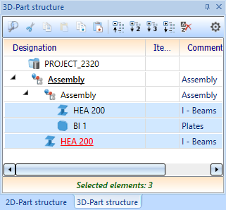
- If multiple parts are selected for processing (multiple selection), the number of selected parts is displayed below the window with the part structure.
2-D/3-D Part structure
By clicking on the symbol, the structure display will unfold, i.e. the subordinate part of a part is being shown. Accordingly, those can be hidden by clicking on the
  symbol.
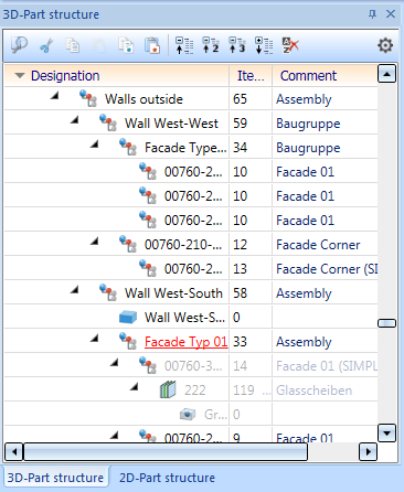
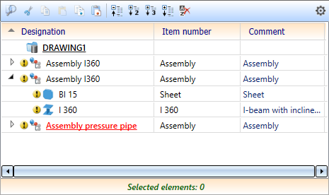
The Part structure is represented in tabular form by default. The ISD default settings are the following columns:
- Designation
contains a graphic symbol for the part type and the article number or rather the part type if the article number is not assigned yet - Item number and
- Comment:
contains the attribute Benennung1 or - in case if the attribute is not assigned - the part type.
Sorting
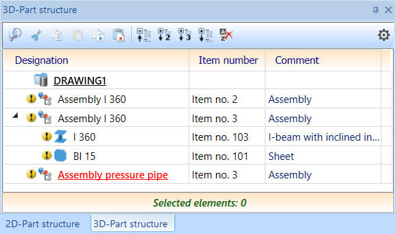
By clicking on a column heading, the sorting of the table can be changed, e.g. descending by position number or ascending by comment. HiCAD remembers the last selected sorting when the program is closed and activates it the next time the program is started. The selected sorting can be cancelled by clicking on  Show unsorted.
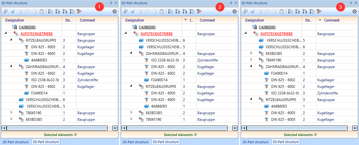
(1) unsorted, (2) item number descending, (3) comment ascending
Toolbar
In the toolbar of the ICN window the following functions are available for the part structure:
|
|
Find Opens the Find part(s) dialogue window |
|
|
Cut (CTRL+X) Cuts the active part (or part list) and puts it on the clipboard |
|
|
Copy (CTRL+C) Copies the active part (or part list) to the clipboard |
|
|
Paste (CTRL+V) Inserts the content of the clipboard. Setzen Sie dazu vorher den Mauszeiger an die gewünschte Position in der Teilestruktur. |
|
|
Copy to HiCAD clipboard Copies the active part (or part list) to the HiCAD Clipboard |
|
|
Paste from HiCAD clipboard Inserts the content of the HiCAD Clipboard |
|
|
Collapse all Collapses the part structure and displays only the first level |
|
|
Expand 2 levels Displays the first two levels of the part structure |
|
|
Expand 3 levels Displays the first three levels of the part structure |
|
|
Expand all Expands the entire part structure and displays all levels |
|
|
Show unsorted Displays the part structure unsorted, i.e. an undertaken sorting will be revoked. |
|
|
Here you can make additional settings for the display, deactivate the tabular display, define the marking of feature and HCM errors or display the HELiOS attributes instead of the HiCAD attributes. |


Settings
By clicking on  you open the dialogue window with the ICN settings.
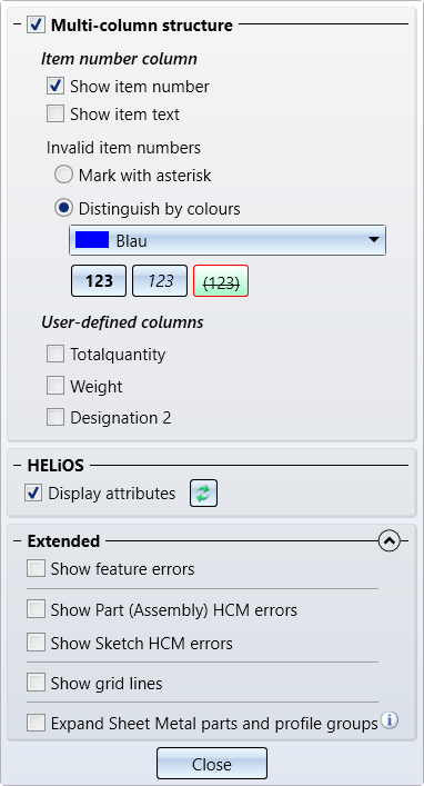
Here you can
- switch the tabular display of the part structure on/off (2-D and 3-D), show the item text in addition to the item number (only in 3-D) and display up to three user columns (only in 3-D),
- switch between displaying the HiCAD and (if available) the HELiOS attributes, and
- define additional settings under Advanced.
Multi-column structure
By deactivating the checkbox, the tabular representation can be turned off. In this case, item number and part type are being indicated in curly brackets, e.g.
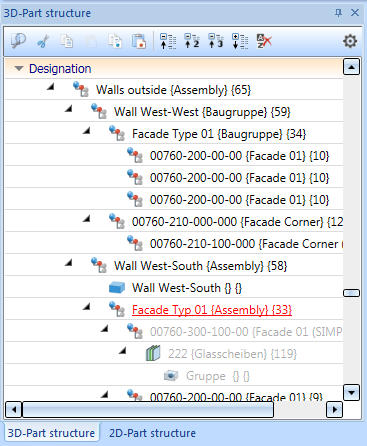
If the Multi-column structure checkbox is active, then - if desired - you can also show the item text in addition to the item number (only in 3-D), specify the marking of invalid item numbers and display up to three user columns (only in 3-D).
Show item number
This checkbox can be used to hide the item number independently of the item text, e.g.
Show item text
This checkbox can be used to hide or show the item text independently of the item number. If the item text is invalid, it is crossed out - just like invalid item numbers. The illustration shows an example with item texts displayed and item numbers hidden.
Invalid Item numbers
Here you can define how invalid, i.e. not current, item numbers are to be marked:
-
with an asterisk * or
- by a colour representation.
Select the desired colour in the list box. You can also change the font styles and variants by activating the buttons below. The fonts and variants boldface, italics and strikethrough are available as well as combinations of these.
Please note that item numbers with no current status are only marked accordingly the parameter Set change mark when changing parts is active in the Configuration Management at System settings > Itemisation > Updating.
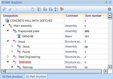
Display user columns
The ICN representation of up to three user columns is supported for the 3-D part structure. The representation can be switched on/off by activating/deactivating the checkbox.
The attributes displayed in the three user columns can be configured individually. The user columns are defined in the HDB files ICN3D_USERn.HDB (for use without HELiOS) or ICN3D_USERn_DB.HDB (for use with HELiOS). n is the number of the user column. The files are located in the HiCAD sys directory.
The following user columns are predefined by ISD:
|
User column |
Attribute |
File without HELiOS |
File with HELiOS |
|
|---|---|---|---|---|
|
1. |
%06 |
Total number |
ICN3D_USER1.HDB |
ICN3D_USER1_DB.HDB |
|
2. |
§01 |
Weight |
ICN3D_USER2.HDB |
ICN3D_USER2_DB.HDB |
|
3. |
$02 |
Designation 2 |
ICN3D_USER3.HDB |
ICN3D_USER3_DB.HDB |
For instance, the number of the shipping item, that is, the item number of the uncut installation profiles (attribute %PI), plays an important role in installation planning. However, the item number (attribute %02) is important for substructures. By defining corresponding user columns, you can display both item numbers in different columns.
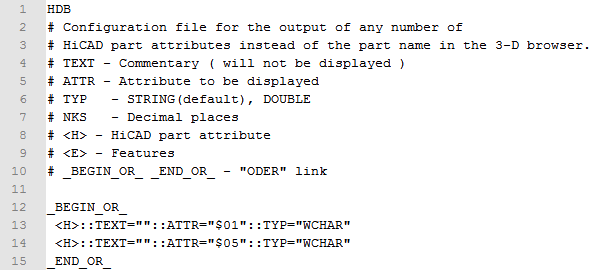
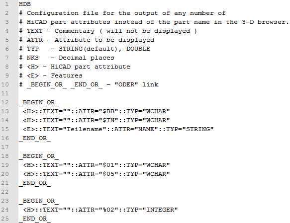
To change the default setting of a user column, click on the corresponding HDB file, e.g. the file ICN3D_USER1_DB.HDB for the first user column:
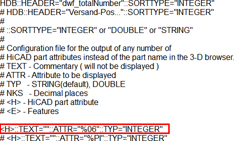
The row highlighted in red defines the contents of the first user column. The ISD default setting is the attribute %06, i.e. the total number. You can also enter the line more than once and mark the other lines as comments by placing the character # at the beginning of the line. In the file shown above, this is already applied for the attribute %PI, i.e. for the number of the shipping item. For example, you could delete the comment character in the %PI line and place it before the %06 line instead. The shipping item number would then be displayed in the ICN in the first user column.
See also HDX and HDB Files and Overview of HiCAD Attributes
Please note that the Total quantity depends on the numbering mode of the itemisation.
Show HELiOS Attributes
Parts administered by HELiOS can be displayed instead of HiCAD Attributes by activating the checkbox. This means that instead of the attributes given in the files
- ICN3D_COMMENT.HDB resp. ICN2D_COMMENT.HDB
- ICN3D_DESIGNATION.HDB resp. ICN2D_DESIGNATION.HDB
- ICN3D_MULTIATTRVIEW.HDB resp. ICN2D_MULTIATTRVIEW.HDB
the attributes from the files
- ICN3D_COMMENT_DB.HDB resp. ICN2D_COMMENT_DB.HDB
- ICN3D_DESIGNATION_DB.HDB resp. ICN2D_DESIGNATION_DB.HDB
- ICN3D_MULTIATTRVIEW_DB.HDB resp. ICN2D_MULTIATTRVIEW_DB.HDB
are being used.
In this case, the button Refresh is additionally available to update the HELiOS Attributes. Please note that HELiOS Attributes are updated automatically when ticking the checkbox for the first time. This may take a moment when working with complex drawings.
Extended
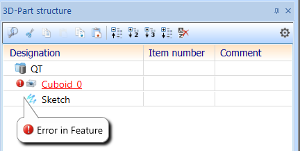
Show Feature and HCM errors
Activating these checkboxes will mark parts with incorrect feature and/or incorrect HCM constraints in the part structure accordingly, e.g.
Show grid lines
To further emphasize the levels of the part structure, grid lines can be displayed by activating this checkbox.

Left: with grid lines, Right: without grid lines
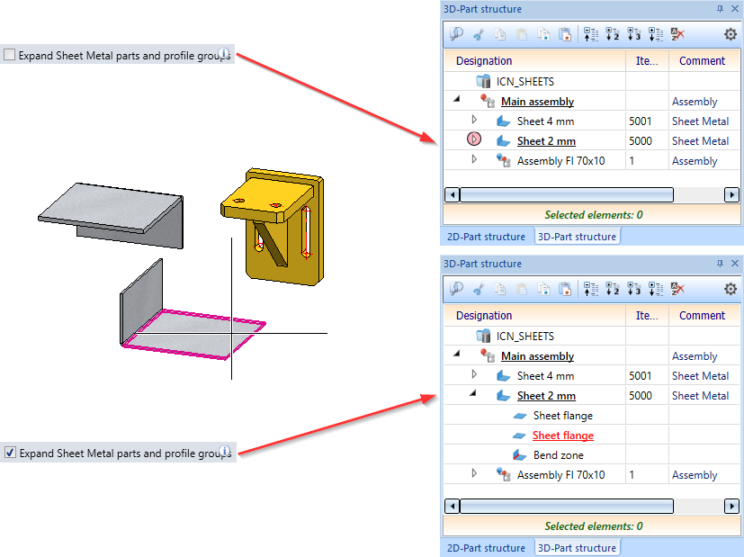
Expand Sheet Metal parts and profile groups
This setting applies only to sheet metal parts and to profiles of a profile group.
Use the checkbox to define whether the structure of the superordinate main part is to be expanded automatically when you select a flange/bend zone of a sheet metal part or a profile of a profile group in the drawing.
If the checkbox is inactive (default), the structure of the superordinate main part is not automatically expanded when a corresponding part is selected, but instead only the superordinate part in the ICN is marked with the  symbol.
Example:
The following drawing consists of a main assembly with 2 sheets and another assembly.
If the checkbox is inactive in the ICN settings, the structure is not expanded when the tab of one sheet is selected.
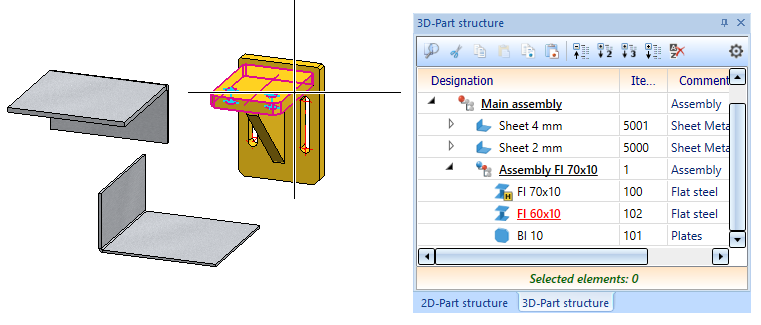
If you select a part of the assembly Fl 70x10, then the structure - as before - is always expanded - independent of the ICN settings.
HDB files for part structure
The representation of the part structure can be adjusted by following system files in the HiCAD sys directory. For the 3-D part structure these are as follows:
- ICN3D_COMMENT.HDB
This files determines the content of the column Comment. The settings predefined by ISD are the export of the attribute Designation1 (Attribute $01) or - if not assigned - Part type($05).
- ICN3D_DESIGNATION.HDB
This files determines the content of the column Designation. The settings predefined by ISD are the export of the attribute Article No. (Attribute $BB) or - if not aissgned - Part name (Attribut $TN).
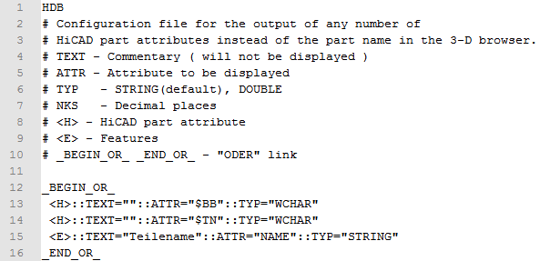
ICN3D_MULTIATTRVIEW.HDB
This file determines which attributes are to be exported if the multi-column structure is deactivated. The default settings predefined by ISD are:
- Export of Article no. ($BB) or Name of part ($TN),
- Export of Designation 1($01) or Part type ($05) and
- Export of Item No.(Attribut %02).
Accordingly, following files are available for database attributes:
- ICN3D_COMMENT_DB.HDB
- ICN3D_DESIGNATION_DB.HDB und
- ICN3D_MULTIATTRVIEW_DB.HDB
For the 2-D part structure following HDB files are available analogously:
- ICN2D_COMMENT.HDB,
- ICN2D_COMMENT_DB.HDB,
- ICN2D_DESIGNATION.HDB,
- ICN2D_DESIGNATION_DB.HDB,
- ICN2D_MULTIATTRVIEW.HDB and
- ICN2D_MULTIATTRVIEW_DB.HDB
When saving HDB files, please make sure that ANSI is selected as character encoding.
Adjustments to the HDB files should only be performed by an experienced administrator!

ICN • Meaning of the ICN Symbols • Colour Display of the ICN Structural Display • Drawing and Parts • Context Menu of the Drawing • System Attributes