Settings - 2-D Drawing Elements
Plant Engineering > Isometry / Pipe Spool Drawing > Isometry settings 
Plant Engineering > Isometry / Pipe Spool Drawing > Pipe spool drawing settings 
Isometry+Pipe Spool Drawing > Settings 
 The following description refers to isometries and pipe spool drawings.
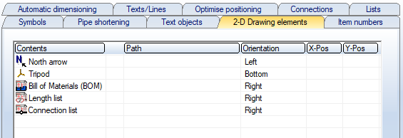
The placement of certain 2-D drawing elements of an isometry within the drawing frame can be preset on the 2-D Drawing elements tab. These are (ISD default setting):
- North arrow,
- Tripod,
- Bill of Materials (BOM),
- Length list and
- Connection list.
In addition, any 2-D drawing additions that are available as FGA files (e.g. logos) can be included and placed in the isometry, e.g.
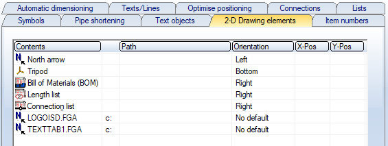
If a file is entered, the corresponding graphic will appear in the isometry after the isometric drawing has been generated.
|
Insert file |
Activate the context menu by right-clicking in the table and select Insert. Then, after clicking on the |
|
Remove file |
To remove a file, activate the context menu with a right click in the corresponding row and select Remove. |
 button in the
 The elements North arrow, Tripod and the three list types cannot be removed from this table. Whether they actually appear in the isometry depends on whether they are activated in the isometry dialogue..
|
Meaning of the columns |
||
|---|---|---|
|
1 |
Contents |
Isometry element or name of the FGA file. |
|
2 |
If the first column contains a file name and the file is located in a HiCAD directory defined in FILEGRUP.DAT, the corresponding indicator is displayed here. |
|
|
3 |
Path |
If the first column contains a file name and the file is not located in a HiCAD directory defined in FILEGRUP.DAT, then the directory path is indicated here. If it is a subdirectory of a HiCAD directory, then only the subdirectory name is shown here and in the 2nd column the indicator of the HiCAD directory. |
| 4 |
Orientation |
Various types of orientation are available here. If you select Position, you can specify the position even more precisely with entries in the 5th and 6th columns. The options "Right" or "Left" positions elements on the sides, one after the other from top to bottom. The option "Top" or "Bottom" places correspondingly at the top or bottom edge, whereby several elements are positioned here one after the other from left to right. User-defined elements (company logos etc.) are always inserted last. Please also read the Notes on BOM orientation in the topic Settings - Lists. |
|
5 |
X-Pos |
If the option Position is selected in the 3rd column (Orientation), the position can be specified here in each case by values between 0 and 100. The reference point is the lower left corner of the drawing frame. 0 stands for left or bottom, 100 for right or top.. |
|
6 |
Y-Pos |
|
Default
Via the Default button, the ISD default setting can be restores at any time. This contains only the elements North arrow, Tripod and the three list types.


Settings (PE/Iso) • Isometry and Pipe Spool Drawing (PE/Iso) • Isometry/Pipe Spool Drawing Functions for the Layout Plan (PE)