Move View
General information
Various options are available for moving views:
|
|
With this function all views within a rectangle can be moved. |
|
|
This function moves the active view or all views of the active part list. The function supports magnetic snap-in and thus simplifies the alignment of views to each other as well as to other additional elements of the drawing sheet such as the drawing and title block frame or part lists. |
|
|
Move individual view or view list via drag & drop Here, a single view or the active view list is moved by dragging and dropping with the mouse. Magnetic snap-in is also supported here. |

You need to distinguish between the following cases when moving views:
- The
active view is a master view
In this case, all views linked to the master view are taken into account. If you only want to move the master view, use the Do not move linked views function.
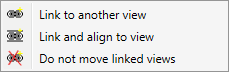
You activate the context menu by right-clicking while the views are hanging on the cursor.
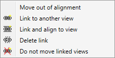
- The active view is linked to a master view.
The active view can then initially only be moved in alignment direction of this master view. If, for example, you have used the 4 views function, the top view is linked to the front view. If you want to move the top view, this is initially only possible in vertical alignment direction. To exit the alignment direction, you use the functions of the Link views context menu.
You activate the context menu by right-clicking while the views are hanging on the cursor.
- The
active view has no links
If the active view has no links, it can be moved in any direction.
When you move a master view, the views linked to this master view will be moved as well.
If you undo the transformation of the master view with the Undo last view transformation![]() function, this action will also affect the linked views.
function, this action will also affect the linked views.

Move views in a rectangle
Views > Transform > Move views, in rectangle 
To move views in a selection rectangle, proceed as follows:
- Draw a rectangle around the views you want to move. All views that are entirely located within the rectangle will be moved.
- Specify the point in the drawing via which you want to move and re-position the view. Once you have selected the displacement point, a preview of the view(s) to be moved attaches to the cursor.
- Then specify the new position of the view(s). Before defining the new position of the views, you can use the right mouse button to activate the Link views context menu, in which you can change the alignment direction.
Move view
Views > Transform > Move > Move view 
With this function you move the active view or all views of the active view list.
Determine the starting point of the relocation, i.e. the point over which you want to move and reposition the view. With the middle mouse button you can also select the spatial centre as the moving point.
The view can then be moved dynamically, with the Magnetic snap-in automatically active. This procedure allows easy alignment with other views or with the optional additional elements of the drawing sheet (drawing frame, title block and BOMs).
- The view edges can be aligned to be flush with each other or with the additional elements of the drawing sheet. If, for example, during dragging a view moves to the same height as an existing view or one of the additional elements, this is indicated in the graphic, e.g. by fading in the horizontal line. If you put the view down, it is aligned with this line. The same applies to vertical alignment.
- Equal spacing does not refer to the geometry but to the view rectangle, i.e. the "envelope rectangle" that completely encloses the view including the annotations etc.

a-c: alignment lines left, centre, right, d: distance line
As soon as a corresponding constellation is created during dynamic moving of a view/view list, graphic auxiliary elements such as distance arrows or alignment lines are displayed. Equal distances are numbered (see the following example). The view can be aligned on the basis of these lines and the desired position can be adopted by lowering the cursor. While moving, the selected view is only displayed as an envelope rectangle.
Example:
The drawing contains four views of a cuboid and a drawing frame with title block.
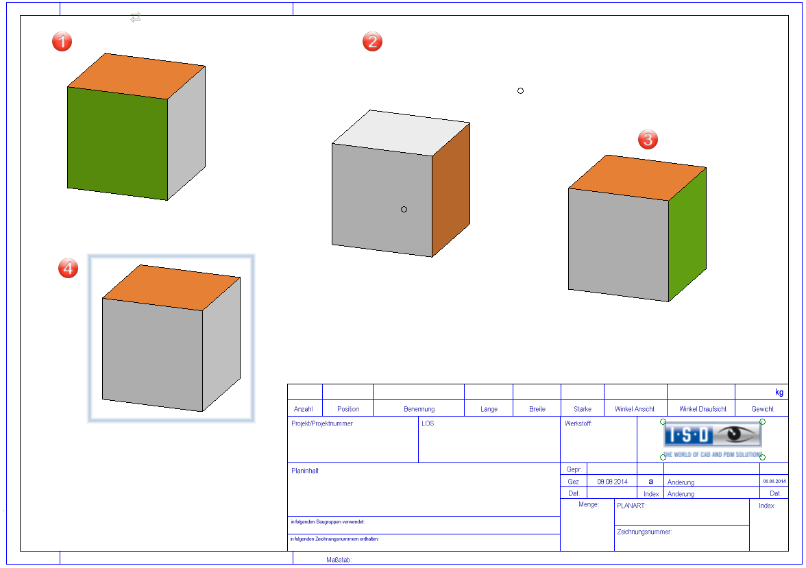
If view 4 is now moved, then - depending on the current cursor position - the alignment and distance lines shown are displayed, for example.
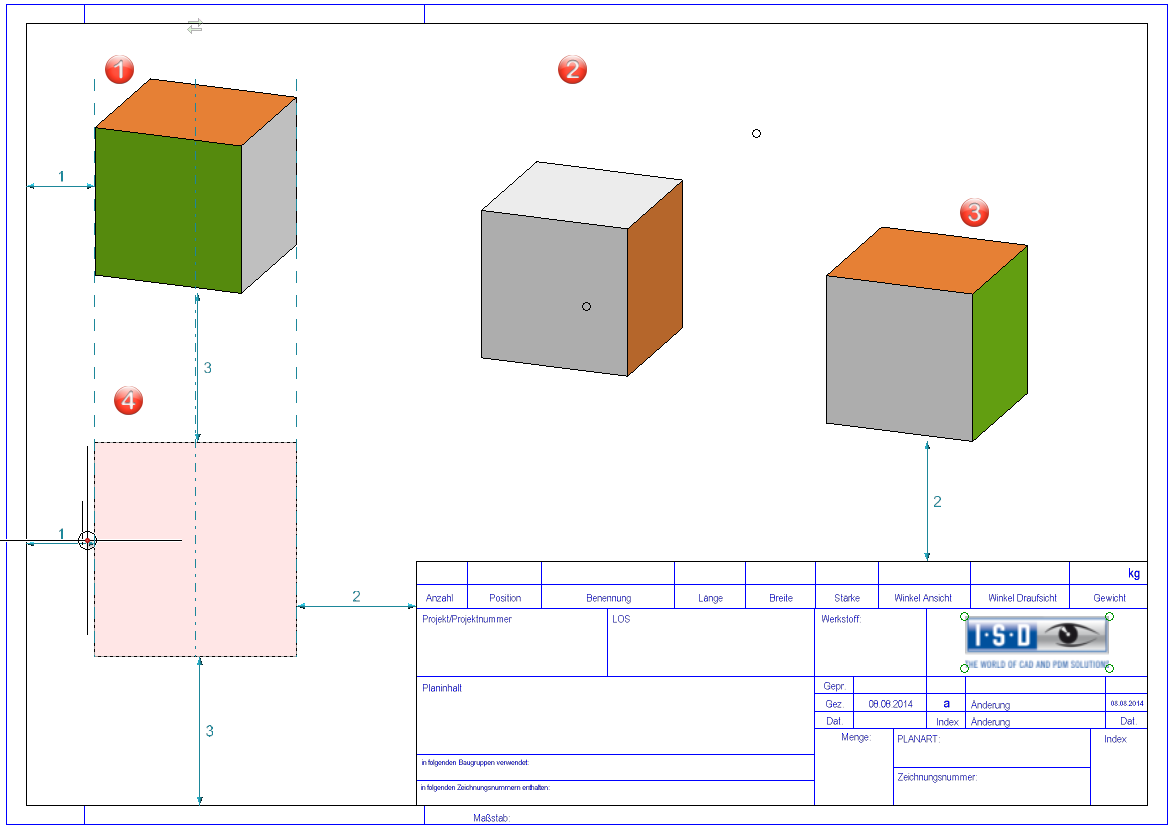
If one were to adopt the depicted cursor position as the end point of the shift, then the lines would have the following meaning or effect:
- View 4 is aligned flush with view 1.
- View 1 and view 4 have the same distance to the drawing frame (distance no. 1).
- The horizontal distance between view 4 and the title block is the same as the vertical distance between view 3 and the title block (distance no. 2).
- The vertical distance between view 1 and view 4 is the same as the distance from view 4 to the drawing frame (distance no. 3).
![]() Please note:
Please note:
- With equal spacing, there are always only three objects involved. The drawing frame is one object.
- Equal distances are only displayed when both ends of the arrow are visible on the screen.
- When aligning one view to another view, the same sides of the view rectangle snap in each case, i.e. left to left, centre to centre, etc. Left to centre is not offered.
-
If a view is aligned, then no further alignment lines are displayed in the direction of alignment.
- By holding down the shift key, you can selectively align horizontally/vertically.
- The magnetic snap-in can be temporarily deactivated during shifting by holding down the Alt key.
- When moving a view list, the alignment lines (left, centre, right) are only displayed for the view that is the first view in the list, i.e. the view that was selected as the first view during selection.
- Before you set the new position of the view, you can activate the View link
context menu with the right mouse button. Here you have the option, among other things, to change the direction of the escape.
Please note:
The alignment is not associative, i.e. the view is not tracked if the object to which the alignment was made changes.
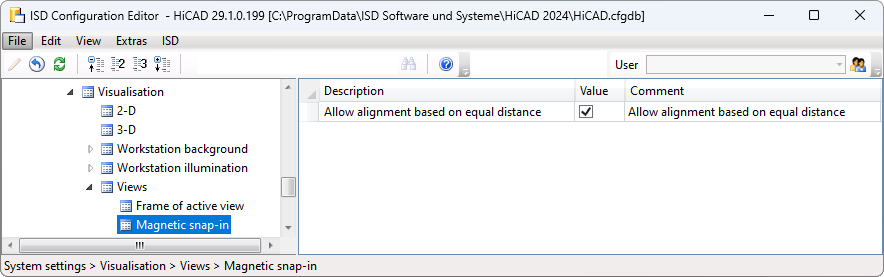
Magnetic snap-in can be switched off in the Configuration Editor. To do this, under System settings > Visualisation > Views > Magnetic snap-in, deactivate the checkbox Allow alignment based on equal distance.
Move view or view list via drag & drop
Views can also be moved directly with the mouse using drag & drop. To do this, click on the view frame with the left mouse button and move the cursor to the desired position while keeping the mouse button pressed.
As with the Move view function, the magnetic snap-in is also active here.
Disable drag & drop
If the drag & drop of views is to be prevented, this can be achieved with the D key. After pressing the key, views are locked against moving by drag & drop during the current HiCAD session. In this state, clicking with the left mouse button on the view frame while holding down the mouse button causes the function Rectangular zoom to be called up. Pressing the D key again cancels this.
![]() Please note:
Please note:
- In contrast to the Move view function, here no points can be caught with the autopilot when determining the end point of the move.
-
View lists can also be moved by drag & drop.

Projections (3-D) • Linked Views (3-D) • View Functions (3-D)