When working with the HCM, some function show a special behaviour. This is described here.

Assembly HCM
- To be able to assign constraints to unsupported geometry types, you can use auxiliary elements, such as isolated points or edges. You can insert these into the appropriate parts and then assign the constraints to these auxiliary elements.
- It is much easier to fix one complete part instead of fixing several individual geometries. This is because you really have to switch off all degrees of freedom via the geometry. You can do this, for example, by fixing three points that do not lie on a straight line or two lines that are not parallel. When fixing geometries, it is often overlooked that despite their fixation, the following displacements are still possible:
- a line along its direction,
- a cylinder along its axial direction,
- a surface freely in its plane.
Change assembly coordinate system
Like every part, an assembly also has a part coordinate system. This coordinate system is either determined automatically by HiCAD or defined by you when creating the assembly. For this purpose, a corresponding parameter is available in the Configuration Editor at Modelling > Part creation > Assembly.
To move the part coordinate system of assemblies, the function Change assembly coordinate system (Drawing > Others > World CS
  > ...) is available.
![]() Important:
Important:
Note that this may also change the geometry and position of the parts in the drawing. Referenced parts change at all points of use.
Example:
Coincidence (3-D Part HCM) exists between a plane of the cuboid and the XY-plane of the part coordinate system of the assembly. If you change the position of the coordinate system, the position of the cuboid will also be adjusted.
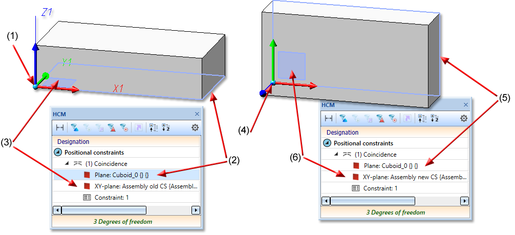
(1) Coordinate system of the assembly, (2) first plane for the coincidence is the lower surface of the cuboid, (3) second plane of the coincidence is the XY-plane of the coordinate system
(4) assembly coordinate system changed, (5) (6) coincidence rotates the plane of the cuboid back to the XY-plane of the coordinate system
