Welded Box Profiles
Steel Engineering > New > Beam  > Welded beams/profiles > Welded box profile
Use this function to insert welded box profiles, consisting of 4 plates (2 webs and 2 flanges). dialogue window will be displayed, enabling you to configure the beam. All data that are relevant for the insertion (distances, dimensions of plates etc.) are clearly marked in the dialogue window.
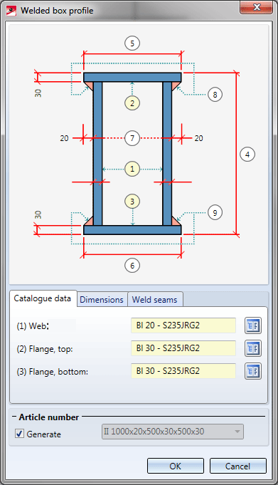
In the Article number field you specify the designation of the beam or profile. If the Generate checkbox has been activated, the article number will be generated automatically. The default setting is
Beam/profile ID Beam/profile height x Web height x Flange width, top x Flange height, top x Flange width, bottom x Flange height, bottom, e.g.
II 1000x20x500x30x500x22
If you want to use a different designation, deactivate the checkbox, and enter the desired article number manually, or enter an already used entry from the list box.
Catalogue data
On the Catalogue data tab you specify the data for the webs and the flanges.
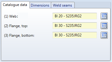
Click the  symbol to select web and flanges directly from the corresponding standard part catalogues - complete with assigned material. The following catalogues are available: :
|
|
Catalogue |
|---|---|
|
Web |
Semi-finished products > Plates |
|
Flange, top |
Semi-finished products > Plates Semi-finished products > Flat steel |
|
Flange, bottom |
Semi-finished products > Plates Semi-finished products >Flat steel |
Dimensions
Here you define the total height of the beam, the width of the flanges and the offset of the flanges relative to the web.
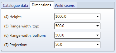
You can enter the desired value directly in the corresponding field, or select an already used value from the list box.
Weld seams
On this tab you specify whether you want weld seams to be inserted and, if so, the way in which you want to insert them. Currently only fillet weld are possible here.
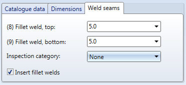
If you want to insert fillet welds, activate the checkbox. Then, specify the thickness of the weld seam ands select an inspection category if desired. The inspection category is required for the generation of weld seam test protocols.
Click OK to start the insertion of the beam. The insertion takes place in the same way as for "normal" standard beams.
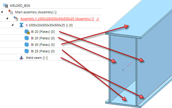
A BOM-relevant assembly will be created for the welded box profile. The name of the assembly is composed of the text Assembly and the article number of the beam, i.e. for example. Assembly II 1000x20x500x30x500x22.Below this entry you will find the actual beam (as a non-relevant assembly), to which the plates (flat steels) have been assigned as sub-parts. One of the plates - normally one of the webs - is the assembly main part.
Example:
 Please note:
- The assemblies created during beam insertion are automatically assigned the Usage Welded box profile. This is of importance for drawing derivations.
- Please note that not all Steel Engineering-relevant processing functions can be applied to welded beams and profiles!
-
Select the object snap or group snap mode option to process the individual plates or the complete beam separately.

- To change a welded beam or profile, double-click the corresponding entry in the feature log. The Welded box profile dialogue window will be displayed again, enabling you to correct the data. In addition, the Total length field is available, enabling you to correct the beam length.

Insertion Options for Beams and Profiles (3-D SE) • Insert Beams (3-D SE) • Settings/Management (3-.D SE)
