Configure and Insert Vertical Ladders
"Civil Engineering" docking window" > Steel Engineering > Stairs+Railings > Stairs > Vertical ladder
Use this function to configure vertical ladders in only a few steps. When you activate the function, the Vertical ladder dialogue window will be displayed:
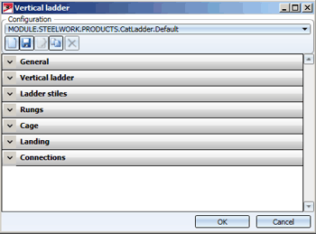
 The default settings for vertical ladders can be specified in the Configuration Editor at Steel Engineering > Products > Vertical ladder.
Manage Configurations of Vertical Ladders
Configuration of vertical ladders are managed in the new ISD Configuration Editor. Such ladder configurations have the name
MODULE.STEEL-WORK.PRODUCTS.CatLadder.xxxx
with xxxx being the designation for the respective configuration. The predefined configuration
MODULE.STEEL-WORK.PRODUCTS.CatLadder.Default
is supplied with HiCAD. This configuration will be active when you call the Vertical ladder function for the first time.
If various ladder configurations are available, you can select a configuration via the listbox at the top of the dialogue window. The toolbar below the listbox provides the following configuration management functions:
|
|
New |
|
|
Save
|
|
|
Rename
|
|
|
Copy
|
|
|
Delete |
Configure Vertical Ladders
You configure the vertical ladder via the buttons of the dialogue window:
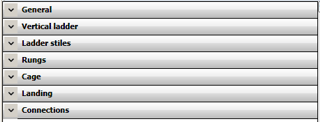
Use the  and.
and.  symbols to expand and collapse the input areas of the buttons.
 Please remember that the fitting of the ladder takes place according to DIN. If one of the entered values is outside the allowed minimum or maximum value range, this will be indicated by the
  symbol. In such cases, please correct you entry accordingly.
General
Here you enter the name of the vertical ladder, e.g. Vertical ladder 12750-R, and select the folder where the KRA files fot the ladder components are located. Click the  icon to select the folder in the Explorer. The predefined part and assemblies can be found in the HiCAD directory KATALOGE > WERKSNORMEN > STAHLBAU > PRODUKTE > STEIGLEITER.
Vertical ladder
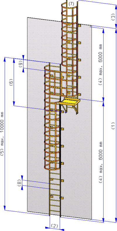
In this area you specify the dimensions of the ladder. These are:
- Building height (1),
- Distance between stiles (2),
- Height above building (3),
- Max. height (4),
- Max height of a section (5),
- Offset between ladder sections (vertical) (6),
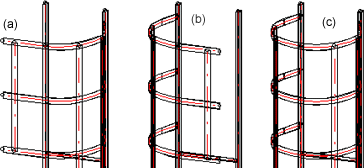
- Type of exit (7) - left (a), right (b) front (c).
Ladder stiles
You use the Stile type listbox to specify whether you want to use a profile from the HiCAD catalogue BEAMS+PROFILES, or a KRA file containing the 3-D part or the assembly for the ladder stile.
- StandardItemHolm
A profile from the HiCAD catalogue BEAMS+PROFILES will be used. The currently set profile is displayed in the Standard row. Click the icon to select a different profile or material.
 - KraPartHolm
A KRA file will be used. Click the icon and select the desired file.
Rungs
Here you specify the distance between the rungs (8) and the distance of the top rung to the stile end (9). As with the stiles, you have the option here to use profiles from the HiCAD catalogue BEAMS+PROFILES, or KRA files as rungs.
Cage
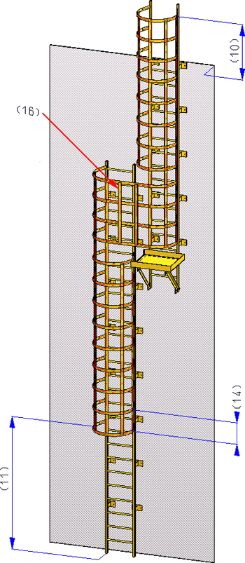
In this section you define the size, as well as other parameters of the security cages of the ladder. These are:
- Height of cage above building (10)
- Height of 1st cage ring above ladder section 1 (11)
- Height of cage (H) (12)
- Cage radius (T) (13)
- Distance between 2 cage rings (14)
- Angle between ladder reinforcements (15)
- KRA files of ring, right ring, left ring and transition. These files must be available as KRA files in the folder shown at the top of the window.
- the Material of the cage rings. You can select the material directly from the catalogue by clicking the icon on the right.
- Position of cage reinforcement on cage ring (16) - inside (a) or outside (b).
Landing
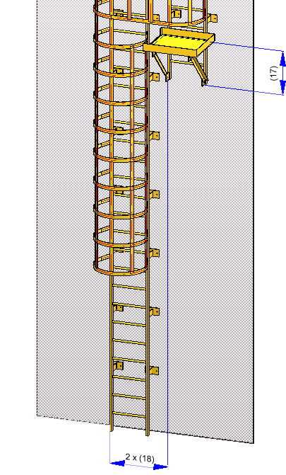
The landing must be available as KRA files for the left and the right cage in the folder shown at the top of the window. Further landing parameters are:
- Height of landing above bottom edge of ladder section (17)
- Offset between ladder sections (horizontal) (18)
Connections
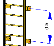
Here you specify the distance between two connections (anchorings) (19) and select the corresponding KRA file of the connection.
Fit Vertical Ladder
After defining all required parameters, click OK to commence the fitting of the ladder. HiCAD starts calculating the ladder.
After completion of the calculation you will be prompted to specify a fitting point on the vertical ladder, and then specify the position of this point in your drawing.
The vertical ladder will be fitted into the drawing as an assembly. Each of these assemblies has the following structure:
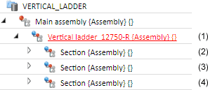
(1) is a superordinate assembly. The part name is the name specified in the dialogue window, the article number is Assembly.
(2) and (3) are the assemblies of the vertical ladder. The article number is the name specified in the dialogue window. The part name is automatically assigned by HiCAD.
(4) Each section of the vertical ladder forms an assembly, which is in turn subdivided into several assemblies.
All assemblies of the vertical ladder are BOM-relevant.

Vertical Ladder (3-D SE) • Create Components of Vertical Ladders (3-D SE) • Change Vertical Ladder (3-D SE) • Stairs and Railings (3-D SE)


