Assemblies, Parts and Attributes
In HiCAD, you basically work with the same user interface and uniform data structures - regardless of which HiCAD module you use. This also applies to steel engineering constructions.
However, you should bear the following special features and notes in mind.
- Main parts and Sub-parts
- Part structure
- Converting assemblies of earlier HiCAD versions
- Part attributes
- Article number for assemblies - Taking over of part dimensions
- Assembly attributes
- Assemblies - Automatic assigning of the usages "Column assembly" and "Girder (beam) assembly
- Structure assemblies

Main parts and Sub-parts
You can insert steel engineering objects into the drawing as both main parts and sub-parts. HiCAD automatically generates the part name. Steel engineering objects like connections, construction aids etc. are usually inserted as sub-parts. Connections, for example, are subordinated to the object identified first.
Steel engineering parts are 3-D parts to which you can also generally apply all 3-D functions
Parts are also selected for processing in the same way as "normal" 3-D parts. This also applies to multiple selection, the part selection filters and the identification mode.
Part structure
The part structure in steel engineering is similar to that in mechanical engineering, i.e.:
- Assemblies
are dummy parts with a special ID. They consist of exactly one main part
– the so-called assembly main part - and
the sub-parts assigned to this part. All BOM-relevant parts of
an assembly are located on one level in the structure; the ID –
main part or sub-part – is assigned internally. assemblies can also
be nested, i.e. an assembly can contain other assemblies.
- If the current drawing is an assembly drawing, it will contain exactly one main assembly to which all other parts are subordinate. This also applies to the fitting of beams.
- If additional parts
like plates and boltings are assigned to a beam via links and
connections, a part of type Assembly will be automatically created. This assembly contains the beam as a main
assembly part and – on the same level in the structure – the other
parts as sub-parts. The assembly is automatically assigned the
sum of the weight of the subordinate parts as an attribute.
If you do not want to use this structure, select Modelling > Change of part structure > Main parts and sub-parts automatically in assemblies: No. Using the structure is, however, recommended for reasons of efficiency.
 As long as no main part has been defined in an assembly, all parts will be considered main parts. Parts which do not belong to an assembly are also main parts.
Converting assemblies of earlier HiCAD versions
If you want to convert assemblies from steel engineering drawings of earlier HiCAD versions (before HiCAD 2007), proceed as follows:
- Load the relevant drawing.
- In the ICN or in the drawing, right-click the part from which you want to derive an assembly and which you want to become the main part of this assembly.
- Select Part/Assembly structure > Form assembly from the context menu.
Part attributes
Unlike other 3-D parts, steel engineering parts are automatically assigned particular part attributes. These include article number, item number, weight, part type, BOM-relevance (yes) etc. The part structure of the ICN therefore displays the article number for steel engineering parts, e.g. HEB 240, rather than the part name. The part attributes are taken into account, for example, during BOM creation
- BOM-Relevance
Steel engineering objects are always assigned the BOM-relevant attribute when they are inserted, irrespective of whether you are working with HELiOS. If you do not want to include a steel engineering object in the BOM, deactivate the BOM-relevant checkbox. - Article
number
The article number for steel engineering parts is displayed in the ICN, rather than the part name. - Part
Type, Description 1, Item number
The part type and the item number are displayed in curly brackets after the article number (or the part name) in the ICN, e.g. {T-beams} {5}. If a value has been assigned to attribute Description 1 in the part attributes, this value is used instead of the part type! - Material
and Weight
If there are material changes, the beam's change of weight is adjusted automatically in proportion to thickness. The same applies to setting the weight calculation, which you can carry out in the Steel Engineering settings on the Weight calculation tab.
Note that these changes only apply temporarily to the current HiCAD session. To change the default setting permanently for weight calculation, open the Configuration Editor, go to Modelling > Part properties and change the settings as required. There you can also specify whether you want the plate waste to be taken into account in weight calculation and, if so, the surface area from which you want this to happen. Changes to this file do not take effect until you re-start HiCAD.
- System
notes
For a number of steel engineering functions, system messages are assigned to the System notes attribute. For example, the text "2 residual piece(s) for metal plate" is entered during the identical part search/weight calculation if the taking into account of residual plate pieces has been activated in the Configuration Editor at Steel Engineering > Weight calculation.
 Attribute configuration according to DSTV Steel Engineering
You can use the HiCAD parameter configuration options to assign DSTV-relevant attributes to the HiCAD attribute masks for parts and drawings. This can be done immediately during the HiCAD installation, by activating the corresponding checkbox in the HiCAD parameter configuration window. In this way, the attribute masks (HDX files in the HiCAD SYS directory) will be preset for DSTV-BOM configuration.
Please note that for an attribute configuration according to DSTV Steel Engineering the Use item number of assembly checkbox at Steel Engineering > DSTV-NC in the Configuration Editor will be activated.
If you want to change the workstation or user configuration subsequently, select Start > All programs > ISD Software und Systeme > Administration > User Parameter Configurator or Computer Parameter Configurator and specify the required settings.
Article number for assemblies
When creating new assemblies, forming assemblies from existing parts and automatically creating assemblies (e.g. for Steel Engineering), the prefix Assembly will be suggested as the default value for the article number. This setting can now be changed in the Configuration Editor at Steel Engineering > Assembly.
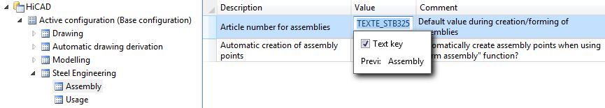
The ISD default setting is the text stored in the HiCAD text key TEXTE_STB325 , i.e. the string "Assembly".
If you want to use your own text instead, simply enter it into the field after deactivating the Text key checkbox.
This setting cannot be applied to main assemblies.
Assembly attributes - Taking over of part dimensions
For automatically created assemblies in Steel and Metal Engineering you can automatically take over the attributes Length, Height and Width from the dimensions of the parts belonging to the assembly, and enter them into the assembly attributes. You can determine in the Configuration Editor at Modelling > Part properties > Calculate assembly dimensions how the assembly dimensions are to be recalculated in case of part changes.
The following settings are possible:
Do not auto-calculate
The attributes of the assembly will not be updated. This is the default setting.
Only when itemising
The attributes will only be updated when an itemisation is performed.
Always
The attributes of the assembly will be recalculated immediately, i.e. after each change to parts or the adding of new parts.
When inserting bolts in an auto-generated assembly in Steel or Metal Engineering, the dimensions of the assembly will be determined by the production type specified in the settings for bolts. If Site assembly has been selected, the part dimensions will not be changed by the insertion of the standard part, i.e. the dimensions will then correspond to the shipping dimensions.
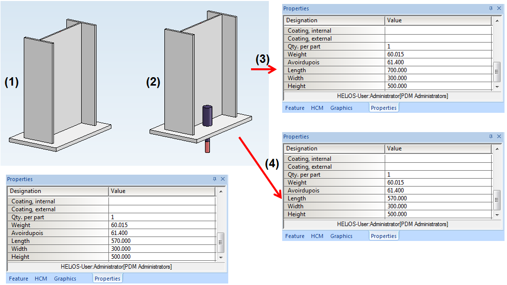
(1) Steel Engineering assembly with original dimensions, (2) Insertion of an anchor bolt,
(3) Dimensions of assembly after insertion of bolt with production type "Factory assembly",
(4) Dimensions of assembly after insertion of bolt with production type "Site assembly".
After applying any changes to the settings at Modelling > Part properties, please restart HiCAD to ensure that the changes will take effect.
Assemblies - Automatic assigning of the usages "Column assembly" and "Girder (beam) assembly
During automatic itemisation you can automatically assign the usages Girder (beam) assembly or Column assembly to Steel Engineering assemblies. For this to happen, open the Configuration Editor and set the parameter at Steel Engineering > Usage accordingly.
- Assign usages COLUMN or BEAM (girder) automatically
If this checkbox is active, the Girder (beam) assembly or Column assembly usage will be automatically assigned to Steel Engineering assemblies - depending on the position of the Steel Engineering main part in the assembly. The checkbox is deactivated by default. - Alignment for columns
Here you select the axis for the alignment of the columns (Default: Z-axis). Beams with this alignment will be recognized as columns, beams standing perpendicular to them as girders. - Allowed angle deviation of beams from defined alignment (in degrees)
This value determines up to how many degrees the axis of a beam is allowed to deviate from the axis specified at Alignment for columns parameter for the beam to be still recognized as a column (Default: 0).
Structure assemblies
A special part type for assemblies is available in HiCAD - the so-called structure assembly. It serves the purpose of structuring HiCAD drawings into construction sections, e.g. Framework, Platform, Column, Platform girders, etc. One advantage of a structure assembly is that can be handled like a non-BOM-relevant assembly - even if it is, in fact, BOM-relevant.
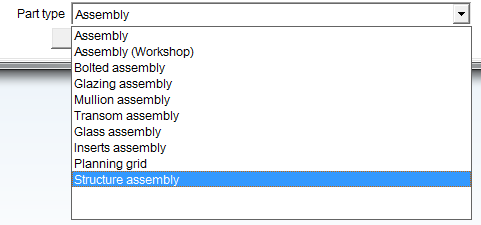
To define an assembly as a structure assembly, use the Part attribute  function in the context menu of the assembly (right-click). In the Part attributes dialogue window, select Structure assembly in the Part type field. Structure assemblies are marked with the
  symbol in the part structure of the ICN.
Advantages of structure assemblies:
- The parts belonging to the structure assembly (semi-finished products) can still be processed and be connected by means of Steel Engineering connections (Design Variants).
- If the parts (semi-finished products) are processed or connected by means of Steel Engineering connections (Design Variants), a BOM-relevant assembly with an unambiguous assembly main part, and the other parts as sub-parts/attached parts on one level will be created for welded parts.
- If a structure assembly contains several semi-finished products, and these are processed or connected by means of Design Variants, an additional BOM-relevant assembly will be automatically created for the welded parts.
- During creation of the BOM-relevant assembly it will be checked whether welded parts already belong to a BOM-relevant assembly. if this is the case, they will be inserted into the already existing assembly.
- If the parts (semi-finished products) are located in a structure assembly, further BOM-relevant assemblies (welded assemblies).
A possible use case:
When inserting Steel Engineering connections between two beams, a BOM-relevant assembly will be created for each of the beams - structured according to DSTV guidelines. This means that the assembly contains the respective beam as assembly main part and - on the same level - the components of the connections belonging to the respective beam. Depending on the fitting situation it can happen in rare cases that a structuring according to DSTV cannot be performed. This can be avoided by the use of structure assemblies.
Important:
Structure assemblies will not be considered in the workshop drawing!
Example:
The image below shows a Steel Engineering drawing - on the left as a "normal" assembly (1), and on the right as a structure assembly.
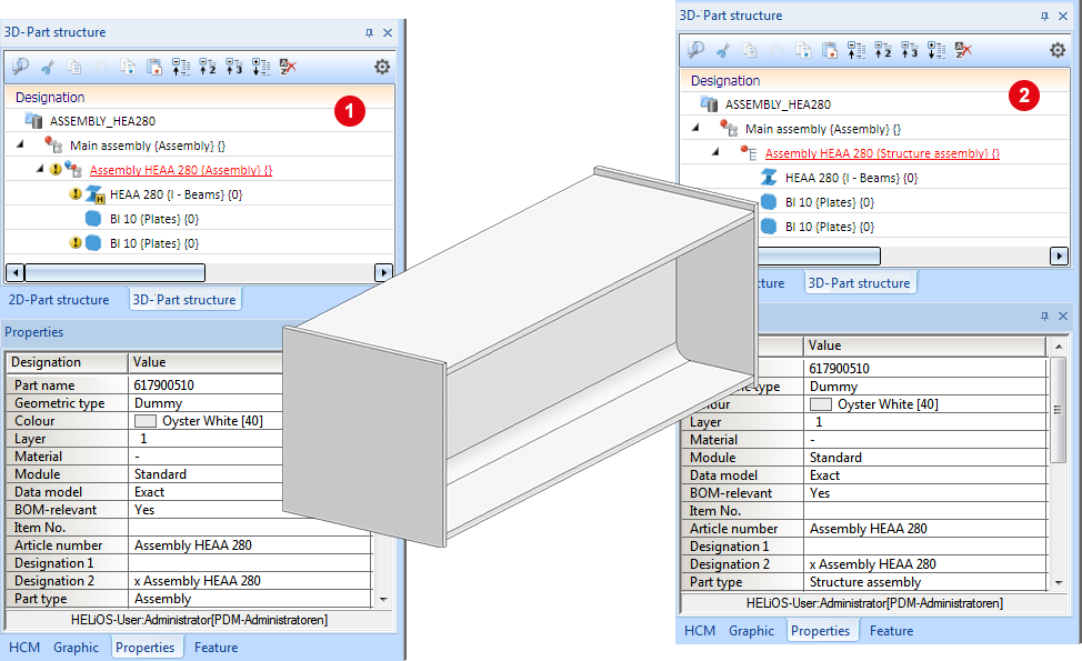
If you now create the workshop drawing with the same settings for both cases, you will see that the structure assembly will not be considered.
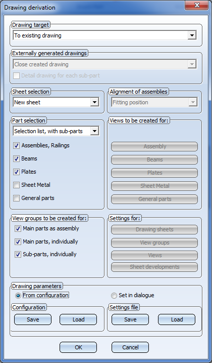
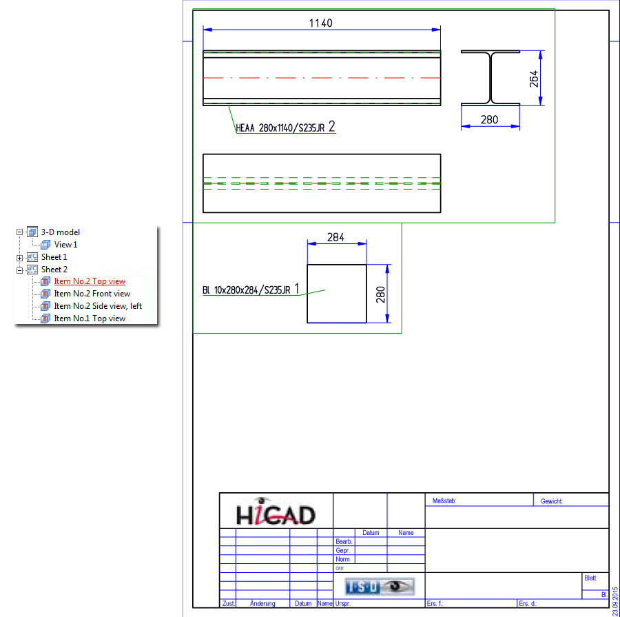
Workshop drawing, Case 1 - Assembly
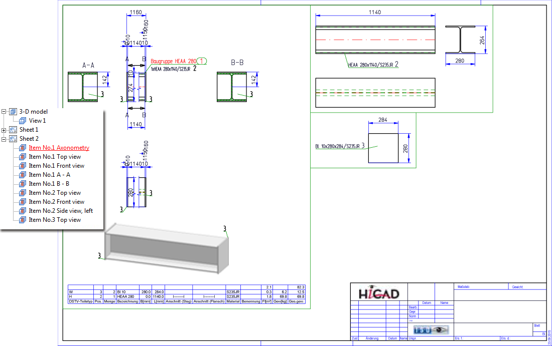
Workshop drawing, Case 2 - Structure assembly

HiCAD 3-D • HiCAD Basics • Notes on the System Files (3-D SE)