Example of a Design Variant for Sheet Metal with Parameterized Part Variables
Step 1: Create construction
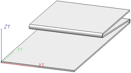
- Create a drawing file and draw a base sheet with the name 001_BLE.
- Then add two flanges with Length 100 and Angle 175°.
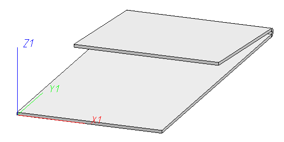
Example of a sheet part
Step 2: Create Design Variant base part
- Create a a dummy part called An1_001 with the function 3-D Standard > New >Dummy part, new (3-D).
- Move the part 001_BLE in the ICN under dummy part An1_001.
- Activate the dummy part.
Now mark the dummy part as design variant base body.
- Right-click in the dummy part's (empty) feature log. Then, activate Design variant base body: YES.
The dummy part is only used as the basis for the design variant in the drawing in which the variant is generated. It is used there, for example, to include the variant's parameter variables. It does not feature in the drawing in which the variant is fitted.
Step 3: Create the part's variables
The design variant base body's variables become the design variant's parameters. In other words, the system prompts for these variables when the variant is fitted. If the variables have a comment, it is displayed instead of the variable name during the prompt.
- In the ICN, activate the part 001_BLE and, in the feature log, move the insertion position under the base sheet.
- Then activate the dummy part An1_001.
The variables need to be set in the dummy part for the design variant.
- Right-click in the dummy part's (empty) feature log. Activate the variant's parameter Parameter variants of variables.
- Activate the Add new variable function. Then, choose Element > Edge and enter, for example, Connecting Edge.
The system then prompts you to specify an edge.
- Identify an edge of the base sheet.
- Enter more variables of the type Number for flange length (Length = 20) and Angle (angle= 180).
Now assign the variables to the elements.
- Activate the part 001_BLE. In the first feature below the insertion position, use the right mouse button to select the edge and activate the Edit formula function.
- Enter the Connecting edge here.
- Now insert the other variables into this feature and let the feature log run to the end
Step 4: Marking the Part as the starting point for processing within the Design Variant
On the one hand, design variants can process one or more parts of the drawing in which they are used and, on the other hand, also introduce new parts into the drawing. The formula entered for the generation feature of the part indicates how to proceed with which sub-part of the design variant base body:
Formula for processed part: All features apart from the generation feature (in this case, the base sheet) are attached to the log of the part in the fitting drawing. The formula determines which part in the fitting drawing. (In this example, the user will doubtless only want to choose the edge to which the addition is to be made. The part therefore results from the formula part_of_edge(connecting _edge).
Formula for assembly: During fitting, the part becomes a sub-part of the part specified in the formula.
- Activate the part 001_BLE. In the feature log, use the right-click to choose the Formula for processed part function.
- Enter part_of_edge(connecting _edge) and choose OK to exit the entry mask.
Step 5: Create Design Variant
- Activate the dummy part An1_001 and, in the feature log, use the right mouse button to choose the Create design variant function.
- Click on the three points following the path for the file name.
- Enter the name attach_flange for the Design Variant im Explorer and select Save.
- In the Save design variant dialogue, select Save again.
The extension for the design variant is FMV (Feature Modifying Variant). As, internally, it is a part that is saved, as was the case with the previous feature variants, the files <name>.FMV.KRP, <name>.FMV.KRP.FEA etc. also exist, in addition to <name>.FMV.
Step 6: Create part variable and insert Design Variant
- Create a new drawing file and draw a base plate with the name 002_BLE. For the depth, right-click in the input field and select Edit formula. Enter Sheet_depth and confirm withOK. Enter 200 as the variable for the sheet depth.
- On the Drawing Ribbon tab, choose Insert Part > Insert part, via Explorer.
- In the Explorer that appears, select the Design Variant Attach_flange.FMV and enter the variables and the connecting edge.
The variables are queried in order (alphabetically). In this example, you must first enter a Connecting_edge then the Length and finally the Angle. After that, the Design Variant will be inserted.
- Then insert the Design Variant a second time.
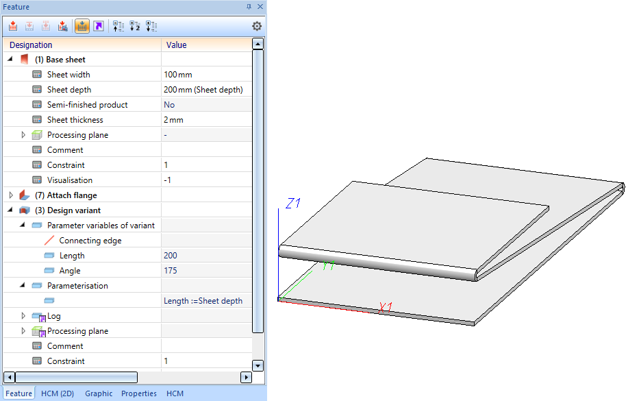
In the log, a feature step called Design Variant is created.. Special sub-items for the Design Variant are:
- Variables table : Double-clicking on it opens a variables table with the variant's parameter variables.
- Log: If you expand the entry you will see the log of the design variant. In particular, the log may contain errors that occurred during insertion..
Step 7: Parameterize Design Variant with part variables
- In the first Design Variant feature, right-click on Parameterisation and choose Add assignment.
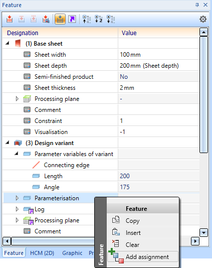
- In the Left side window, enter the parameter variable of the variant, i.e.Length and exit the window by clicking OK. In the Right side window that then appears, enter the variable of the part, i.e. Sheet_depth , and then click OK.
If you change the part variable Sheet_depth , the Length of the Design Variant will also be adjusted.

