Special Situations
Special situations can occur with some functions when working with the feature log. These are described here.

Point numbers at isolated points
When creating an isolated point with a point number, the Point number attribute of the Isolated point feature is set instead of creating a separate log entry for it
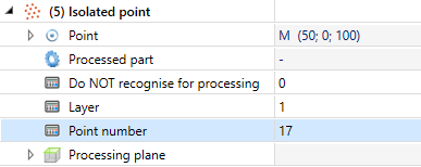
This is also handled accordingly by the Delete point number functions, so that they now empty the Point number attribute. This has the consequence that the deletion of point numbers remains even after a feature recalculation.
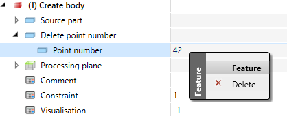
Special cases here are parts whose feature log was activated when points and point numbers were already created. If you delete point numbers in this situation, they will be entered as a separate Delete point designation entry at the Create body feature. Here you can delete individual deleted point numbers via the Delete context menu functions or delete the entire list via the Clear function, whereby the point numbers are restored at the latest with the next feature recalculation.
Working with different units
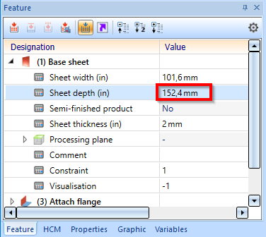
If a part is inserted into a drawing created with a different unit, this will be indicated in the feature ICN by displaying the original unit.
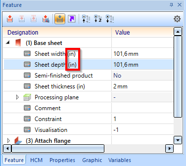
A Sheet Metal part created in an inch drawing is inserted into a millimetre drawing.
The change of values is done with the pocket calculator in the original unit.
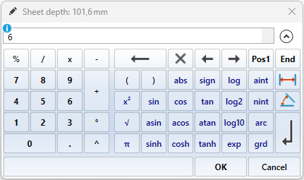
The depth of the sheet is changed from 4 to 6.
If, for example, you change the feature of a cone in the creation dialogue, the original unit will also be displayed here.
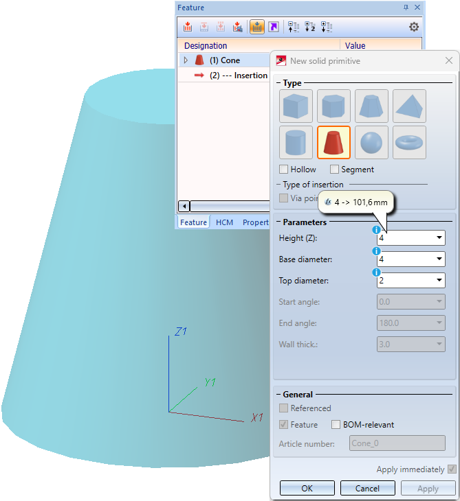
In dialogues, input fields containing deviating units are indicated with a blue info icon.
Change assembly coordinate system
Like every part, an assembly also has a part coordinate system. Until now, this coordinate system could either be determined automatically by HiCAD or set by you when creating the assembly. For this purpose, a corresponding parameter is available in the Configuration Editor at Modelling > Part creation > Assembly.
You can also move the part coordinate system of assemblies with the new function Change assembly coordinate system  (Drawing > Others > World CS
  > ...).
![]() Important:
Important:
Note that this may also change the geometry and position of the parts in the drawing. Referenced parts will change at all points of use.
Example of a feature with external reference:
The isolated point set with the point option K refers to the part coordinate system of the assembly. If you change the coordinate system, the position of the point and all elements that refer to the point will also change.
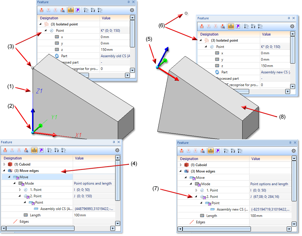
(1) Part of Assembly, (2) Coordinate system of Assembly, (3) isolated point refers to the Assembly CS, (4) Feature Move edges with external reference to Isolated point
(5) Assembly CS changed, (6) as a result, the position of the Isolated point changes, (7) Feature Move edges with external reference to Isolated point, (8) Geometry is adjusted accordingly
