Sheet Metal > Further functions > Extras  > Welded corner
Use the Welded corner function to create a welded corner between two flanges of a Sheet Metal part. The flanges can have different lengths and bend angles. For such cases you can choose between different types of transitions.
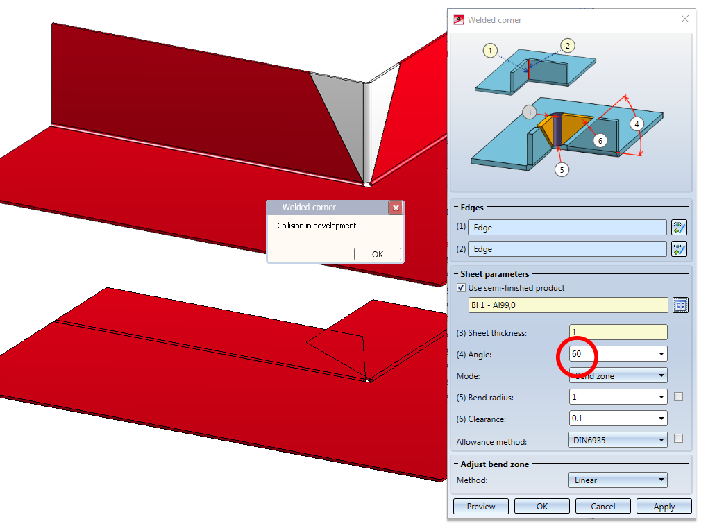
When you activate the function the following dialogue window will be displayed:

The areas of the dialogue window:

Edges
- Identify the two sheets, each at one of the two longitudinal edges of the front side.
If you want to identify a different front side, click the  icon in the Edge area of the dialogue for identification.
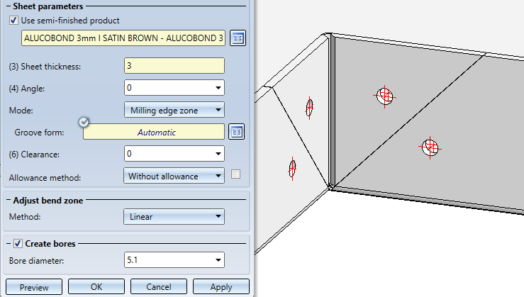
Sheet parameters
If you click on the  icon you can take the standard for the semi-finished product from the Catalogue Editor. The selection of the semi-finished product influences the sheet thickness, the material and the article number. A double-click on the Welded corner entry in the Feature log allows you to activate or deactivate the semi-finished product later.
- Enter the Sheet thickness for the welded corner.
- Enter the Angle for the welded corner.

(1) 60° angle of welded corner
(2) 45° angle of welded corner
The welded corner will also be inserted in cases where the affected flanges of the original sheet collide in developed state. In such cases an error message will be issued:
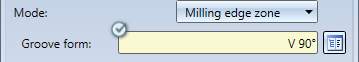
- Choose the Mode of the bend zone.
Composite sheets (e.g. ALUCOBOND® panels) are deformed by using milling edges. The resulting bend zones differ geometrically from the cylindrical bend zones. Therefore, HiCAD offers the option to choose between bend zones and milling edge zones.
The following modes are available:
|
|
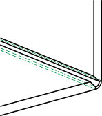
Bend zone The bend zone has the specified bend radius. |
|
|
|
Milling edge zone Bend zone with the chosen tool (milled inside). |
|
|
|
Milling edge zone, inverted Bend zone with the chosen tool (milled outside). |
|


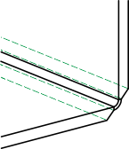
If you have chosen Milling edge zone as mode, the outer contour of the sheet in the area of the bonded / riveted edges is subtracted for the milling cutter in the welded corner..
Development with material subtraction for milling cutter
Use the Groove form option to choose the matching tool for the milling edges from the catalogue Factory standards > Composite panels, groove form.
- Enter a Bend radius for the bend zone.
- Enter the Clearance for the weld material.
- Choose an Allowance method.
To preserve the development of the welded corner, HiCAD offers a development according to different calculation methods ("Allowance methods") that consider the material-dependent length changes of the workpiece that occur during the bending process. In HiCAD, the practice-oriented allowance methods are available for the selection.
Each allowance method is represented by a corresponding system file. These files have been prepared according to an example; in practice, however, it can be assumed that users will want to save one or several, user-defined files. Before applying the welded corner you can choose a system file here.
Adjust bend zone
- If the flanges have different lengths, specify the handling of the bend zones.
The following options are available for a processing of flanges with different lengths or angles:
|
|
Planar |
The front surface of the bend zone will be pulled back perpendicular to the axis. |
|
|
Linear |
The front surface of the bend zone connects both flanges. The result is a planar front surface. |
|
|
Bulgy (inside) |
The front surface of the bend zone connects both flanges. The result is a concave front surface. |
|
|
Hollow (outside) |
The front surface of the bend zone connects both flanges. The result is a convex front surface. |


Create bores
Since composite panels are usually bonded or riveted, you now have the option of inserting bores.
- If you have selected a composite sheet for Semi-finished products, you can activate the option Create bores and select a bore diameter
- Then, specify the bore diameter.
Apply/discard changes
- Confirm your inputs with OK.
Once you have entered all required data, you can create the welded corner. Click Apply to insert the welded corner, while the dialogue window remains open, allowing you to make further changes if desired. Click OK to insert the welded corner and close the dialogue window. Click Cancel to close the dialogue window and discard all inputs, without creating the welded corner. Click Preview to update the welded corner after changes in the dialogue window.
![]() Please note:
Please note:
Incorrect inputs will be indicated by the  symbol. Move the cursor over the symbol to display the error message.

If the function cannot be executed with the entered data, the  symbol will be displayed next to the OK button. Move the cursor over the symbol to display the error message.

Example:

(1) Welded corner
(2) Feature log
(3) Double-click the Welded corner Feature to open the dialogue window
