Sheet Metal > Attach > AlongSkt  > Along sketch
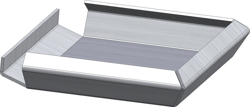
With this function you can attach several flanges around a surface in one step. The flanges are derived from a planar sketch and are chamfered taking into account the current Technology parameters.
The parameters such as angle, bend zone or milling edge zone or fitting mode can be set individually for each flange if required.
After calling the function, the Flanges along sketch on surface dialogue window is displayed.
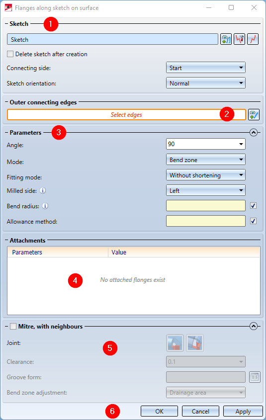
The dialogue window consists of the following areas:

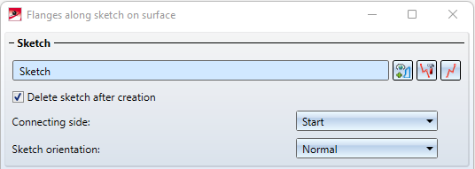
Sketch
- After calling up the function, select a plane sketch. 3-D sketches are not permitted.
If the active part when calling the function is a sketch, then this is already selected.
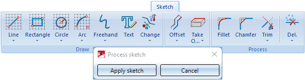
You can also call the function New sketch in plane in the dialogue window and draw a new sketch with the sketching tool. Then end the sketching tool with Apply sketch. To change the sketch, click on the Process sketch
  icon. The menu bar with the sketch functions and the processing dialogue are displayed. You also end the sketch processing via the dialogue window.
If you want to select another sketch, click on the  icon in the Sketch area and select the desired sketch.
|
Connecting side |
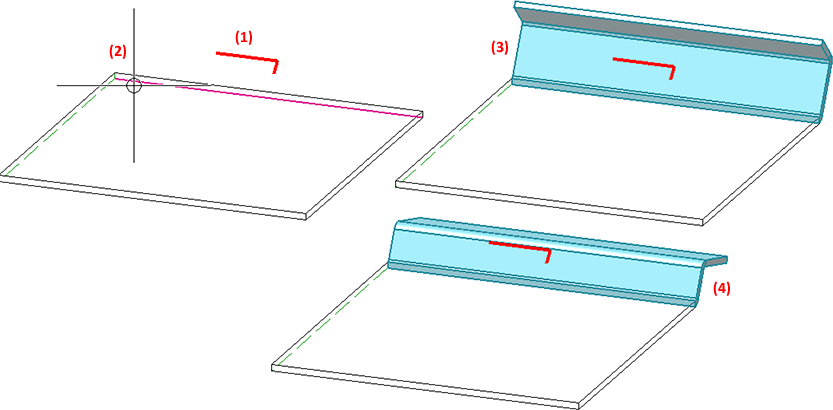
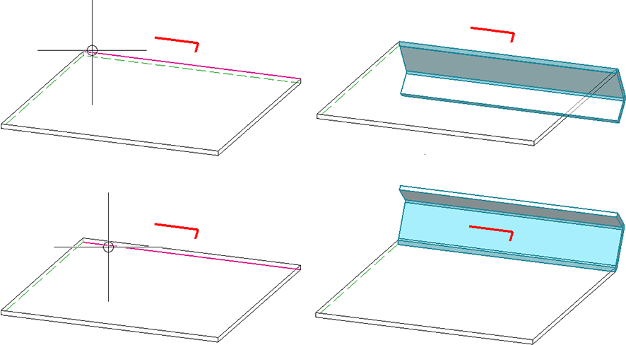
Here you can choose whether the start or end point of the sketch is attached to the connecting edge.
(1) Sketch, (2) Connecting edge, (3) Connecting side = Start, (4) Connecting side = End |
|
Sketch orientation |
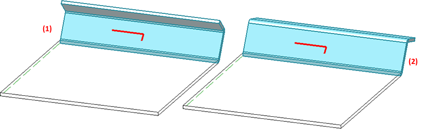
The orientation of the sketch is determined by Normal or Inverted.
(1) Sketch normal , (2) Sketch inverted |
|
Delete sketch after creation |
Activate this checkbox if the sketch should be deleted after the creation of the flanges. The feature log can be used to edit the sketch even after it has been deleted. |
Outer connecting edges
Here you determine the edges to which the flanges are to be attached.
- Select either the top surface of a sheet metal part or the desired edges. The choice of edges is also decisive for the direction of the flanges.
The number of selected edges is displayed in the input field. To select more edges, click on the icon. If an already selected edge is selected again, the edge is removed from the selection. Click on the  symbol to delete the entire selection.
After selecting the sketch and connecting edge, a preview of the new flanges is displayed immediately.
Parameters
In this area you define the settings for the flanges to be created. In the Attachments area (see below), you can then adjust the settings for the individual flanges individually.
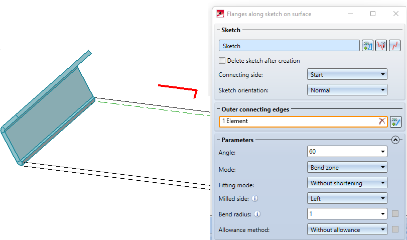
- Enter the bend angle, the bend radius and the mode (bend zone or milling edge zone) in the input window.
|
Angle |
Here you enter then bend angle of the new flange. |
||||||||||||||
|
Mode |
Here you can choose between bend zone and milling edge zone. In practice, the milling edge zone is used for composite panels. |
||||||||||||||
|
Fitting mode |
Here you determine the fitting mode of the flanges (also see Attach Flange and Bend Zone
|
||||||||||||||
|
Milled sideSeite |
For the milled side which will only be evaluated for milling edge zones, the direction of the sketch is decisive. |
||||||||||||||
|
Bend radius |
The bend radius will only be evaluated for bend zones. |
||||||||||||||
|
Allowance method |
In order to obtain the blank (development) of the modelled sheet metal part, HiCAD offers you the processing according to different calculation methods (so-called allowance methods), which take into account the material-dependent length change of the workpiece that occurs during bending. HiCAD offers the empirical allowance methods which are also common in practice. A specific calculation method is represented by a system file. These files are prepared as examples, but in practice every user will store one or more methods in this way himself. You can select a system file here before you click on it. |


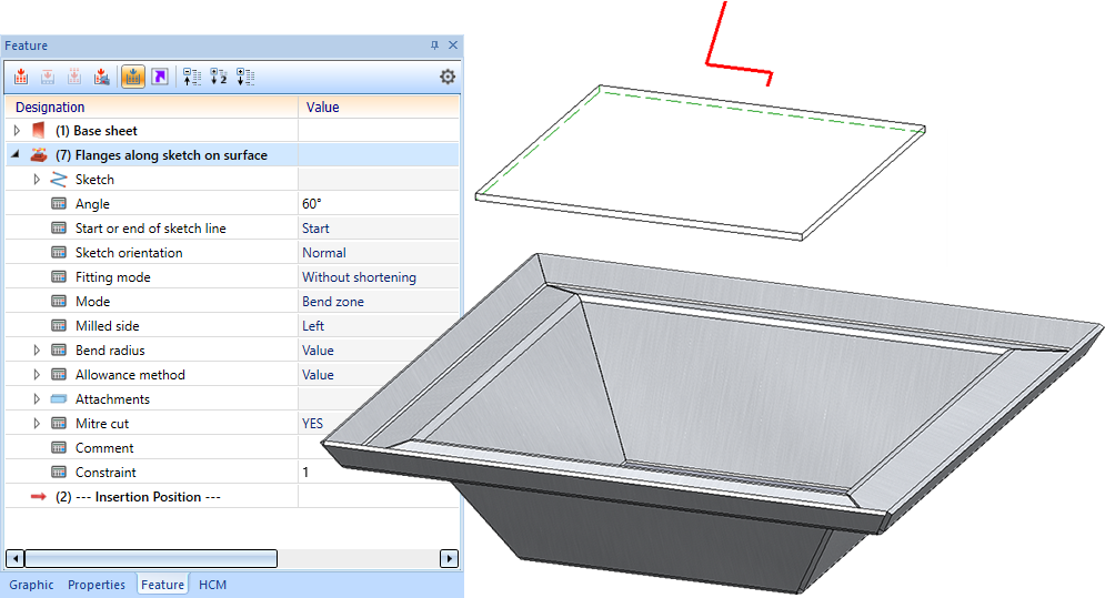
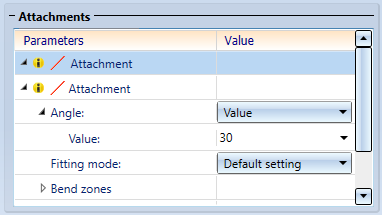
Attachments
The attached flanges are listed here for each selected edge.
In the example below, the 4 edges of the base of the sheet have been selected.
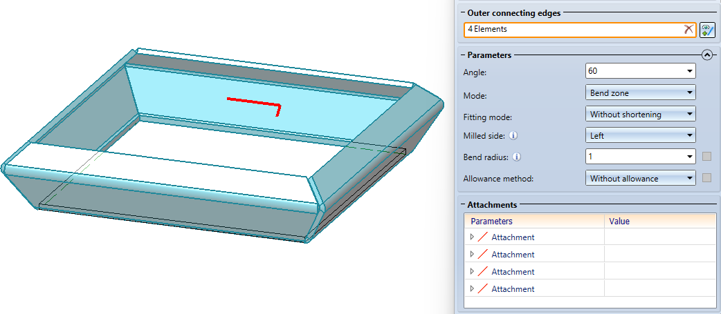
Each of these edges has an entry under Attachments. If you click on an entry in the list, the corresponding flange is highlighted in the drawing. For each flange, the data specified under Parameters are initially preset. If you click on the arrow symbol of an attachment, the parameters are displayed and can be individually adjusted for the currently selected attachment.
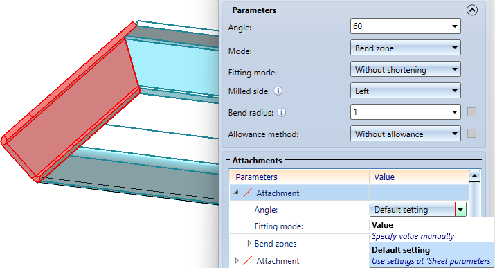
With Default setting, the value entered under Parameters or the selected setting is applied. With Value the setting for this attachment can be adjusted.
Attachments whose settings differ from the data entered under Parameters are marked with the  symbol.
Mitre, with neighbours
Here you can define how sheet metal parts and bend zones/milling edge zones are to be mitred by activating the checkbox. The bend zone is either cut or adjusted.
The Joint determines whether the inner edges of the flanges are shortened or lengthened flush ![]() or, in the case of composite panels, end with a milling edge zone
or, in the case of composite panels, end with a milling edge zone ![]() . For the milling edge zones, you can select the appropriate milling tool from the catalogue with the Groove form option: Click on the
. For the milling edge zones, you can select the appropriate milling tool from the catalogue with the Groove form option: Click on the  symbol and choose Factory standards > Composite panels, groove form.
The following options are available for adjusting the bend zone or milling edge zone:
|
|
Planar, shorter flange: The front surface of the milling edge zone is retracted perpendicular to the axis. |
|
|
Planar, longer flange, längere Lasche: The front surface of the milling edge zone is pulled forward perpendicular to the axis. |
|
|
Hollow (outside): The front surface of the milling edge zone connects both flanges. The result is a convex front surface. |
|
|
Bulgy (inside): The front surface of the milling edge zone connects both flanges. The result is a concave front surface. |
|
|
Linear: The front surface of the milling edge zone connects both flanges. The result is a planar front surface. |
|
|
Drainage area: The front surface of the milling edge zone connects both flanges. The result is a closed corner. |
|
|
No adjustment: The front surface remains unchanged. |


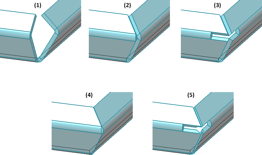
(1) without mitre,
(2) Joint: Inner edge, flush, Bend zone adjustment: Drainage area,
(3) Joint: Inner edge, flush, Bend zone adjustment: No adjustment,
(4) Joint: Sheet edge as milling edge, Groove form: V 90° acute, Bend zone adjustment: Hollow (outside)
(5) Joint: Sheet edge as milling edge, Groove form: V 90° acute, Bend zone adjustment: No adjustment
Apply/discard inputs
Once you have entered all the necessary data, the new flanges can be installed as shown in the preview. If you select Apply or press the middle mouse button, the flange is installed, but the dialogue window remains open - in contrast to OK. This way you can change the data and assign it to another connecting edge with Apply. If you close the dialogue window with Cancel, the function will be cancelled without any insertion or modification.
![]() Please note:
Please note:
Incorrect entries are indicated by the  symbol. Move the cursor over the symbol to display the error message.

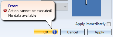
If the function cannot be executed with the entered data, the  appears at the OK button. Move the cursor over the symbol to display the error message.