Sheet Metal > Further functions > Extras  > Bend zone tooling
With the Bend zone tooling function you control the assignment of bending tools to bend zones. In the HiCAD Sheet Metal module, the angle, the bending radius and the allowance method are defined for bend zones. In practice, the bend radius depends, for example, on the material, the thickness and also the bending tools used. To take this into account, you must first enter the data of the tools in the Catalogue Editor. Then the function can be called and the data stored in the catalogue can be assigned. The data set in this way can then be output in the development.
![]() Please note:
Please note:
The input data for the catalogue is not supplied by the ISD.

Example: Assigning a bending tool
Preparing the data in the catalogue
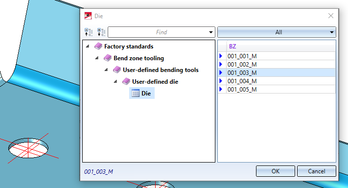
In the catalogue there are prepared tables for die and punch which you can fill with the data of your processing machine. The tables can be found in the catalogue at Factory standards > Bend zone tooling > User-defined bending tools.
- Die: Tool parameters of the die
- Punch: Tool parameters of the punch
Assigning the bending tools
After calling the function, the input mask appears. The bend zones of the active part are displayed. If you want to identify another sheet metal part, select the icon  for identification in the Sheet area.
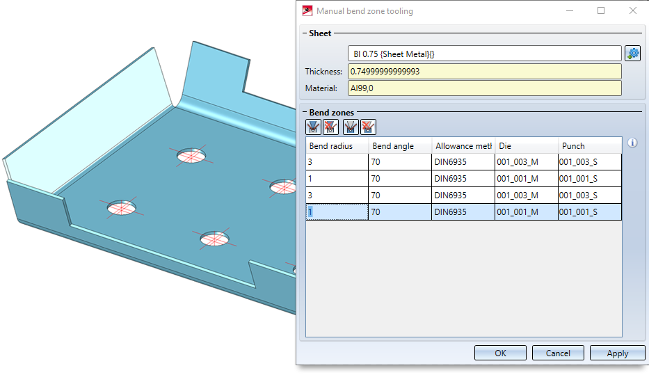
To assign the tools, activate the bend zone. If you hold down the CTRL key, you can activate several bend zones by clicking on them. Then select the icon for e.g. Die  . The data stored in the catalogue are then offered for selection.
Accept the data for the die with OK. Then select the icon for the stamp  and assign the stored data to it from the catalogue.
|
Icon |
Description |
|---|---|
|
|
Select the die from the factory standards and assign it to the active bend zones. |
|
|
Delete the assignment of the die to the bend zone in the active bend zones. |
|
|
Select the punch from factory standards and assign to the active bend zones. |
|
|
Delete the assignment of the punch to the bend zone in the active bend zones. |


If you have entered the required data for die and stamp, the assignment can be applied. If you select Apply or press the middle mouse button (MMT), the data will be assigned, but the dialogue window will remain open - unlike OK. This way you can select another sheet metal part. If you leave the dialogue window with Cancel, the function is cancelled without any assignment taking place.
![]() Please note:
Please note:
If the function cannot be executed with the entered data, this symbol  appears at the OK button. Move the cursor over the symbol to display the error message.

Example: Creating developments with output of die and the punch
The bending tools Die and Punch defined in the Bend zone tooling can be displayed in the bend line text of the development.
The selection is made in the Development settings dialogue when editing the bend line texts.

Then select the attributes Die and Punch in the Text Editor:

If a bend zone tooling exists for the bend zone, the names of these tools can now be inserted into the bend line text.
The names are the entries of the column BZ in the corresponding bend zone tooling tables "Die" and "Punch" from the Catalogue Editor.


