Please also read the notes on the following topics:
- Base points on hidden sub-parts
- Attached sheet/plate parts or plates and beams bordering on relevant beams
- Separate chain dimensions for different usages
- Separate dimension chains for bores and subtractions
- Separate dimensions according to part type for position of sub-parts
- Dimensioning and annotation for hidden bores and processings
- Position of dimension chain

Base points on hidden sub-parts
In the file STW_DIMSETTINGS.XML you can specify how base points on hidden parts are to be handled when using dimensioning rules. To do this, enter the following string into the file:
</PARAM><PARAM Name="IGNOREHIDDENSUBPARTANDBORES" Typ="INT" Value="0">
If Value has been set to 1, base points that are located on hidden sub-parts will not be considered for dimensioning in all dimensioning rules.
Attached sheet/plate parts or plates and beams bordering on relevant beams
When dimensioning attached sheet/plate parts or plates and beams that border on dimensionally relevant beams, both contact points will always be dimensioned. If only the first contact point in the chain is to be dimensioned, open the STW_DimSettings.XML (conventional dimensioning settings) file in the HiCAD sys directory and set the parameter
</PARAM><PARAM Name="SUBPARTPOSITION" Typ="INT" Value="0">
to 1.
This setting affects all dimensioning rules marked with an asterisk *
.
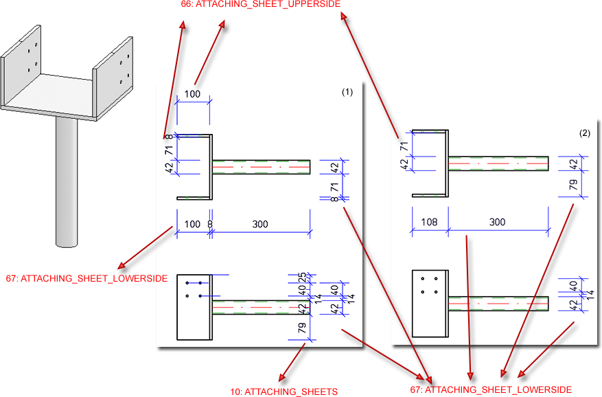
Beispiel - (1) ohne Änderung der STW_DimSettings.XML , (2) mit Änderung der STW_DimSettings.XML
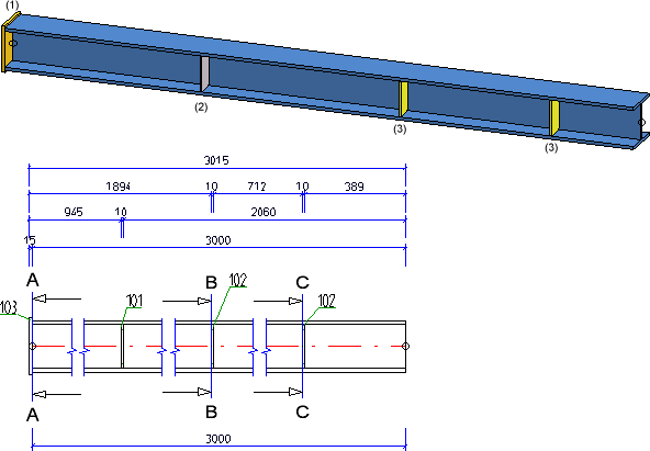
Separate chain dimensions for different usages
You have the option to create separate chain dimensions per different usage for chain dimensions describing the fitting situation of parts. To change this behaviour, open the STW_DimSettings.XML (conventional dimensioning settings) file in the HiCAD sys directory and set the parameter SEPERATEDSUBPARTPOSITION to 1:
</PARAM><PARAM Name="SEPERATEDSUBPARTPOSITION" Typ="INT" Value="1">
The image below shows a beam with 4 plates for different usages (1=Front plate, 2=Reinforcement plate, (3) Stiffener) and the front view of the production drawing.
If the STW_DimSettings.XML file does not contain the described parameters, you can also make manual entries as described above.
Separate dimension chains for bores and subtractions
In the Dimensioning Settings it is now possible to determine under Bores/Boltings that separate chains of dimensions should be created for bores (through holes and standard bores) and subtractions. For this purpose there is the Separate dimension chains for bores and subtractions checkbox.
For new installations or when the dimensioning settings file STW_DIMSETTINGS.xml is not yet available, the stab3par.dat option can be switched on and off under
Maßketten für Lage der Bohrungen/Ausnehmungen trennen nach Bohrungen und Ausnehmungen 1:ja, 0:nein
If the STW_DIMSETTINGS.xml file is available, the line
</PARAM><PARAM Name="DEVIDEBORESANDCUTS" Typ="INT" Value="1">
has to be added.
This settings will not yet be saved in the workshop drawing at this point!
Please note that this setting also affects the following dimensioning rules:
|
12 |
Bores in web of beam |
PROFBORES_INWEB |
|
15 |
Bores in upper and lower flange of beam |
PROFBORES_INFLANGES |
|
34 |
Bores in sheets/plates, right or left side |
SHEETBORES_RIGHTANDLEFT |
|
37 |
Bores in sheets/plates, upper or lower half |
SHEETBORES_ABOVEANDBELOW |
|
49 |
Outer contour of sheets/plates, right and left side, in sectional views |
SHEETOUTLINE_RIGHTANDLEFT_IN_SECT |
|
50 |
Outer contour of sheets/plates (sub-parts), top and bottom side, in sectional views |
SHEETOUTLINE_ABOVEANDBELOW_IN_SECT |
|
85 |
Beam processing in web, incl. processings in side view |
PROFBORES_INWEB_VERT |
|
88 |
Beam processings in upper and lower flange, incl. processings in side view |
PROFBORES_INFLANGES_VERT |
|
98 |
Bores in web of relevant beam sub-parts |
PROFBORES_INWEB_RELVPROFS |
|
101 |
Bores in flanges of relevant beam sub-parts |
PROFBORES_INFLANGES_RELVPROFS |
Example - Separate chains of dimensions for bores and subtractions
The depicted drawing (1) contains several through holes bores and one rectangular subtraction. (2) separate chains of dimension, (3) one chain of dimensions for bores and subtractions
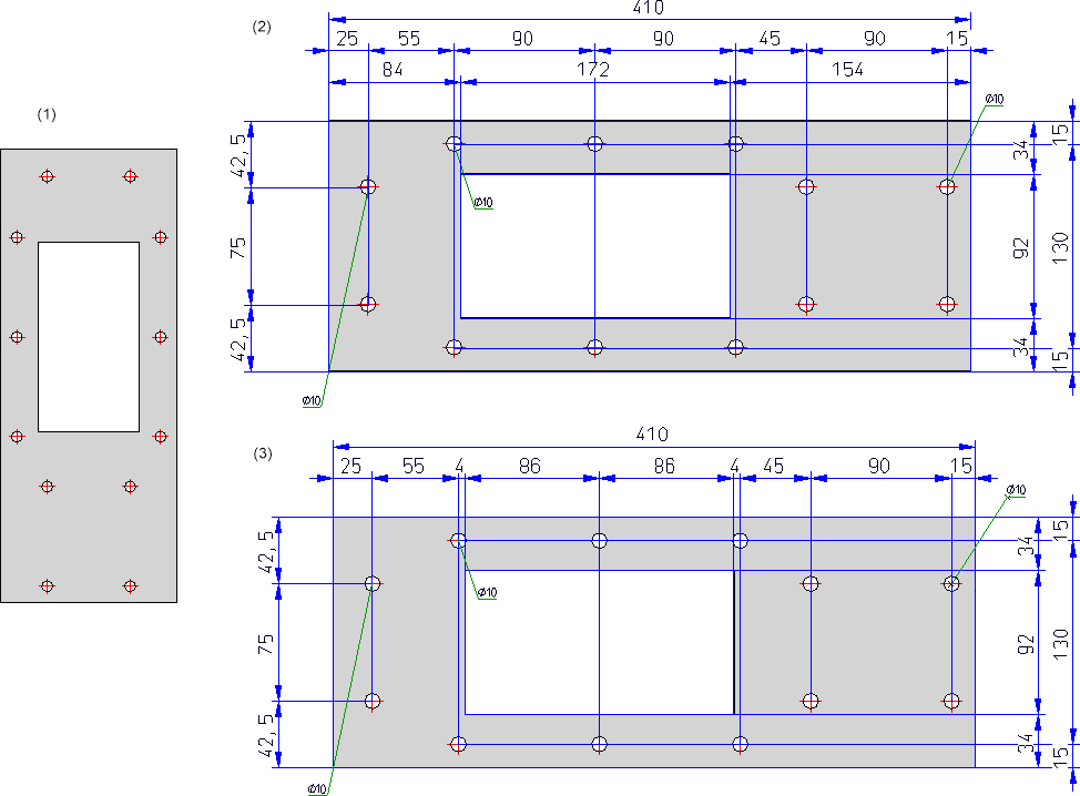
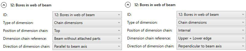
In the example the following settings for dimensioning rule 12 have been used for (3):
Separate dimensions according to part type for position of sub-parts
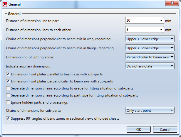
In the Dimensioning Settings it is now possible to determine under General that attached parts (beams) will be dimensioned according to the Part type attribute in the different chains of dimensions. A respective checkbox is available in the dialogue window. In this way it is possible to dimension hollow profiles / attached parts separately from round steel / attached part, thus improving the dimension structure.
This setting affects dimensioning rules for chains of dimensioning of relevant parts.
For new installations or when the dimensioning settings file STW_DIMSETTINGS.xml is not yet available, the stab3par.dat option can be switched on and off under
Separated chain dimensions according to part type for position of sub-parts 1:yes, 0:no - Getrennte Massketten nach Teileart fuer Einbausituation von Nebenteilen 1:ja, 0:nein
If the STW_DIMSETTINGS.xml file is available, the line
</PARAM><PARAM Name="SEPERATEDSUBPARTPOSITION_PT" Typ="INT" Value="0">
has to be added.
Dimensioning and annotation for hidden parts and processings
Dimensioning and annotations for beams, plates and sheets in workshop drawings can (if desired) be placed only on the visible outer side, i.e. bores/processings that are displayed with dashed lines in the HiddenLine dashed representation will not be dimensioned in the corresponding view.
To suppress the dimensioning for hidden parts and processings, the following requirements must be met:
- In the dimensioning settings, the option Ignore hidden parts and processings must be unticked.
This corresponds in the file STW_DIMSETTINGS.XML to the line </PARAM><PARAM Name="IGNOREHIDDENSUBPARTANDBORES" Typ="INT" Value="0"> or in the file STAB3DPAR.DAT (new customers) to the entry ignore base points on invisible parts and bores? 1:yes, 0:no
- The part/processing must be entirely hidden. If it is partly visible it will be dimensioned!
The settings for the dimensioning only apply to dimensionings via dimensioning rules.
To suppress the annotations for hidden parts/processings, the following requirements must be met:
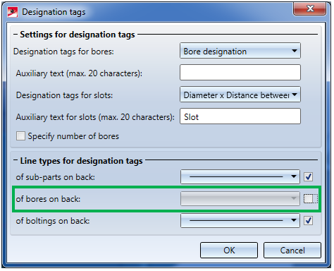
- In the Dimensioning Settings the line type for annotation tags of bores located on the back must have been switched off.
- The HiddenLine or HiddenLine dashed representation must have been chosen.
- The part/processing must be entirely hidden. If it is partly visible it will be annotated!
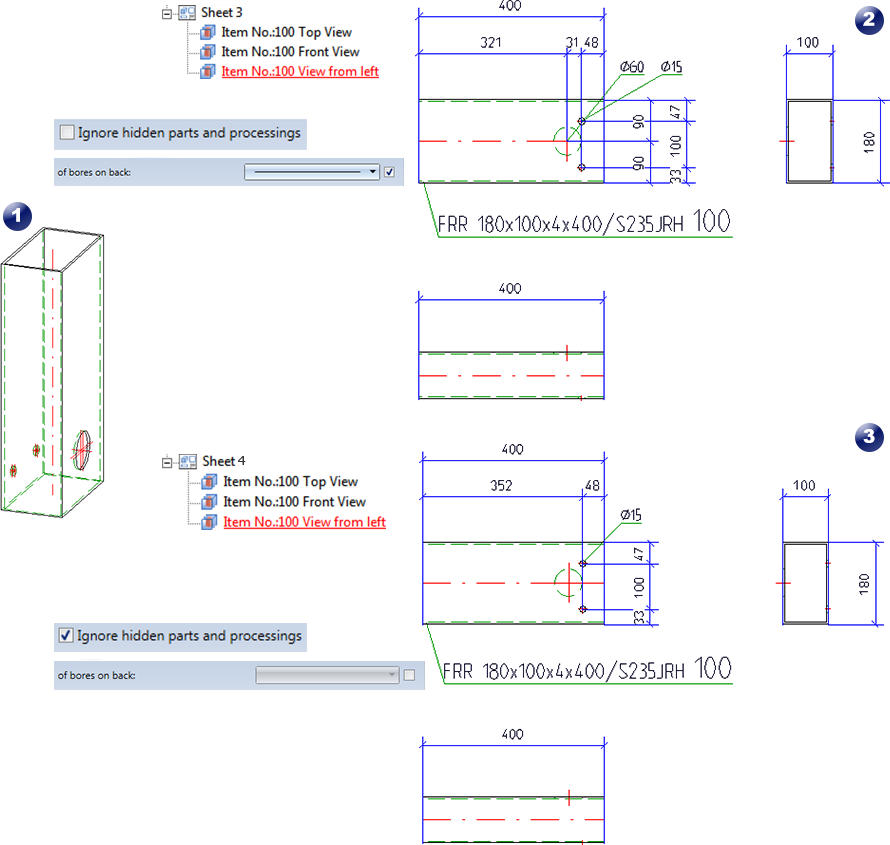
(1) Original beam; (2) Workshop drawing with suppressed dimensioning + annotation of hidden parts; (3) Without dimensioning + annotation of hidden parts
Position of dimension chain
Via settings for Dimensioning rules - either in the Configuration Management or Dimensioning Rules Editor - it is also possible to set only the upper or lower edge for attached parts or even the beam axis as position. Please note that top and bottom refer to the coordinate system of the sheet rather than the beam.
Contour dimensioning
The selection of base points has changed for the automatic dimensioning of contours. This change applies to applies to sheet metal parts, steel engineering plates and glass panes.
Until now, when dimensioning contours, the end points of the individual edges were dimensioned. However, this is usually not desired in practice. From SP2 onwards, the following base points are therefore taken into account when dimensioning contours:
Outer contours
-
Lines running perpendicular to the dimension line
- Extreme points of outer contours that lie in the dimensional direction (also points lying on an arc or freeform line)
- All points with a bend
Except for inverse curves, where the centre lies on both adjacent lines. - Theoretical intersection points of curves in the outer contour
For each arc that is tangentially adjacent to a straight line on both sides, the theoretical intersection point of the two lines is dimensioned if the angle of the two lines is greater than 50 degrees (i.e. not for very acute angles only). When merging with other dimensions, theoretical intersections are removed first, which affects the length of the projection lines.
Bores/Subtractions
- Centres of circles, bores and slots
Depending on the setting specified at Drawing > Itemisation/Detailing > Dim... > Dimensioning Settings
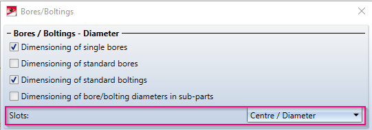
- Lines, points and theoretical intersection points as for outer contours
This change concerns the dimensioning rules for outer contours and bores/subtractions of sheet metal parts (and their developments), steel engineering plates and glass panes.
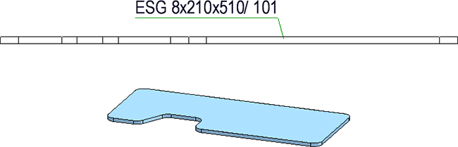
Dimensioning of outer contour, before HiCAD 2020 SP2
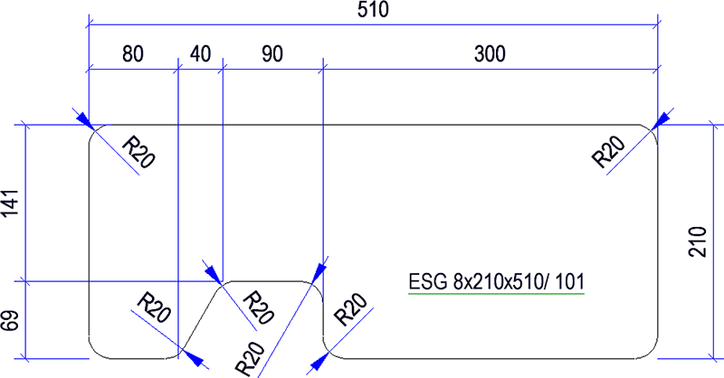
Dimensioning of outer contour with HiCAD 2020 SP2

Drawing Derivation • Derived Drawing: Change Settings • Drawing Derivation: Dialogue Window