Scale and Unit of Measurement

Scale list selection
HiCAD supports both metric scales commonly used in Europe and imperial scales used in North America. Which scales are available for selection in HiCAD is defined in the Configuration Editor at System settings > Scales. There you can define different scale lists and specify which of these lists should be the active scale list. This list will then be used by default for new model drawings in HiCAD.
Three scale lists are predefined by the ISD:
- Standard scales, metric (1)
- Extended scales, metric (2) and
- Standard scales, imperial (3)
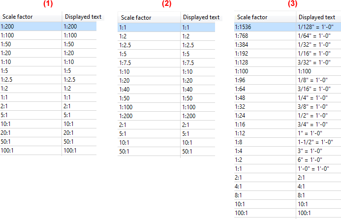
The default active scale list is Standard scales, metric.
The scale of a model drawing is defined when the drawing is created. If you work with Start Centre, you can select the scale there. The scales defined in the active scale list are offered for selection. When working without Start Center, the scale last selected there is used. The scale of a model drawing can be changed later with the Main scale function.
![]() Please note:
Please note:
- The unit of length, the scale and the origin of the coordinate system also define the image detail.
- Scales are used in HiCAD not only as the main scale of a model drawing, but also as the
- scale of a view,
- scale of a 2-D part,
- scale of Steel Engineering detail drawings,
- scale of production drawings and mounting drawings,
- and many more.
- The scale can be selected from a selection box in the corresponding HiCAD function dialogues. In many cases, it is also possible to enter a scale directly. Which scales are displayed in the selection boxes of the HiCAD functions depends on which scale list is selected as the active scale list in the Configuration Editor.
For more information on the scale, refer to the Create and Edit Scale Lists topic. Please also observe the notes listed there.
Main scale
Drawing > Properties > Main scale 
With the Main scale function you can subsequently change the scale of the current model drawing.
- Select a scale from the list box or enter the desired scale in the input field. If only one number is entered, the scale is set to 1:1.
- Exit the window with OK.
Alternatively, you can also find the function in the context menu for drawings.
Which scales are offered for selection depends on the settings in the Configuration Editor at System settings > Scales.
Scale and unit of length of the current drawing are displayed in the status bar at the bottom of the window:

Note:
If you right-click in the input field for the scale, the function Add scale is available. With this function you can define further individual scales for the current drawing without having to leave the scale function. How this is done is explained in the section Manage drawing scales.
In the topic Create and Edit Scale Lists it is explained how to create drawing-independent scale lists.
Manage drawing scales
Drawing > Properties > Scale  > Manage drawing scales
The selection of a scale is usually done via a selection box. Which scales are listed there depends on which scale list is preset as active scale list in the Configuration Editor at System settings > Scales.
If you want to adjust this scale list only for the current model drawing, use the function Manage drawing scales. The changed scale list is then valid for the current drawing and is saved together with the drawing.
After calling the function the dialogue window Manage drawing scales is displayed.
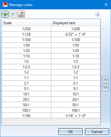
The column Scale shows the scale factor. The column Displayed text contains the text that is displayed in the selection box for scales in the various functions instead of the corresponding scale. This text may differ from the text in the Scale column. In this way, country-specific designations for scales can be stored - as shown in the image above.
The order of display in the selection boxes can be changed with the arrow keys on the left of the dialogue window.
|
|
Add scale Inserts a new line. Then enter the scale and the display text. Please note that the scale must be unique. If this is not the case, the symbol appears in the corresponding row. |
|
|
Remove scale Removes the scale in the currently selected row. |
|
|
Show/hide displayed text Shows/hides the column with the displayed text. |


If the dialogue window is closed with OK, the changed scale list is taken over for the current drawing and saved with the drawing.
The function can also be called directly within certain scale functions. To do this, right-click in the scale field in the dialogue of the corresponding function and select the function Add scale in the context menu. In this way, further individual scales can be defined for the current model drawing without having to leave the current function.
This is possible for the following functions:

 2-D part scale and


Coordinate Systems • Zoom Functions • Create and Edit Scale Lists