Settings - Texts/Lines
Plant Engineering > Isometry / Pipe Spool Drawing > Isometry settings 
Plant Engineering > Isometry / Pipe Spool Drawing > Pipe spool drawing settings 
Isometry + Pipe spool drawing > Settings 
 The following descriptions do also apply to pipe spool drawings.
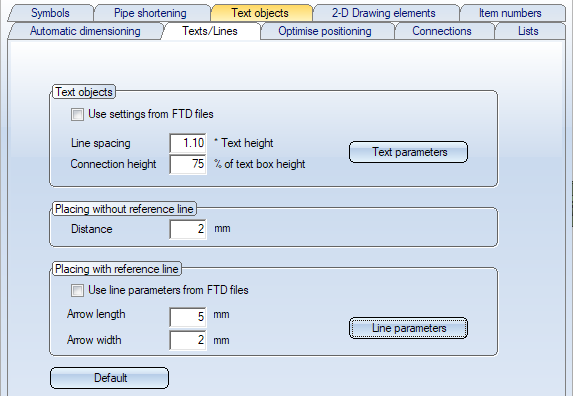
With the settings of the Texts/Lines tab you determine how text objects are to be displayed in isometries and pipe spool drawings.
A text object is a 2-D text (also multi-line) that is assigned to a 3-D point in a 3-D part. The text can be framed and optionally created with a reference line that connects the 3-D reference point in the graphic to the text object, also via several bend points. Optionally, an arrowhead can point to the 3-D point.
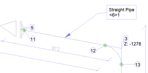
The assignment to the 3-D part has the effect that the 2-D text object is always automatically placed in the correct position even if the 3-D view is changed and the reference line adjusts its route accordingly.
Please noteSie:
The content of these text objects is basically determined by the FTD files assigned to the part types on the Text objects tab. The settings on the Texts/Lines tab only influence the optical representation of the text objects, e.g. the font or the line type of the reference line.
Text objects
The representation of the text objects can - similar to 2-D or 3-D annotation - be done via templates - the so-called FTD files. For each part type you can define which FTD file is to be used for the corresponding text objects in the isometry and in the pipe spool drawing. You define this assignment on the Text objects tab. If you want to use the text settings defined in the FTD files for the display of the text objects, activate the checkbox Use settings from FTD files.
If you want to use the same display for all part types, deactivate the checkbox. In this case you can define the display by clicking on the Text parameters button.
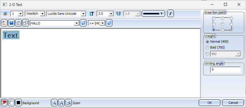
As in the 2-D Text Editor, you can specify the following settings here:
- the layer, the encoding, the font, the text height and colour as well as the text style (italics),
- the insertion point of the text,
- whether and to what extent the text should be displayed in bold (Weight)
- the text inclination. This determines the font style and the slant of the text (Writing angle).
Select the desired settings and exit the window with OK.
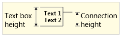
When using the text parameters, you can also determine the factor for the line spacing (factor* x Text height) and the connection height (in % of text box height).
Placing without reference line
If the text objects are to be displayed without a reference line, you can enter the distance of the text box from the part here.
Placing with reference line
If you want to use the settings from the FTD files for the line parameters - colour, line type and layer as well as arrow size - of the reference lines, which you have assigned to the part types on the Text objects tab, activate the checkbox Use line parameters from FTD files.
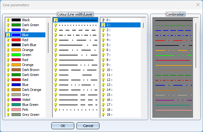
If you want to select the same line parameters for all part types, deactivate the checkbox. In this case you can enter the arrow length/width and select the colour, line type and layer of the reference line after clicking the Line parameters button..
To restore the ISD default settings, click Default at the bottom of the Texts/Lines tab.
Please note:
When subsequently moving and editing text objects in the isometry or in the pipe spool drawing, the current settings on the Texts/Lines tab are always used. These may differ from the settings that were current when the isometry or pipe spool drawing was created.


Settings (PE/Iso) • Isometry and Pipe Spool Drawing (PE/Iso) • Isometry and Pipe Spool Drawing Functions for the Layout Plan (PE)