Plant Engineering > Guideline Tools > Guide.  > Create guideline
Guidelines have been created as 3-D sketches in Plant Engineering since HiCAD 2021. The Create guideline function is used for this purpose.
3-D sketches require a part coordinate system to which, for example, the grid during sketching or possibly assigned HCM constraints refer. In general, when creating a 3-D sketch, it is necessary to specify a plane in which the sketch is to be drawn. This determines the part coordinate system of the 3-D sketch (also sketch coordinate system).
During pipeline planning, this step tends to inhibit the workflow, so as of SP1 - in contrast to 3-D sketches - this step can be bypassed for guideline sketches. Nevertheless, such a sketch coordinate system is also required for guideline sketches, since the origin of this coordinate system is used for the calculation of HCM constraints that relate the edges of a sketch to each other.
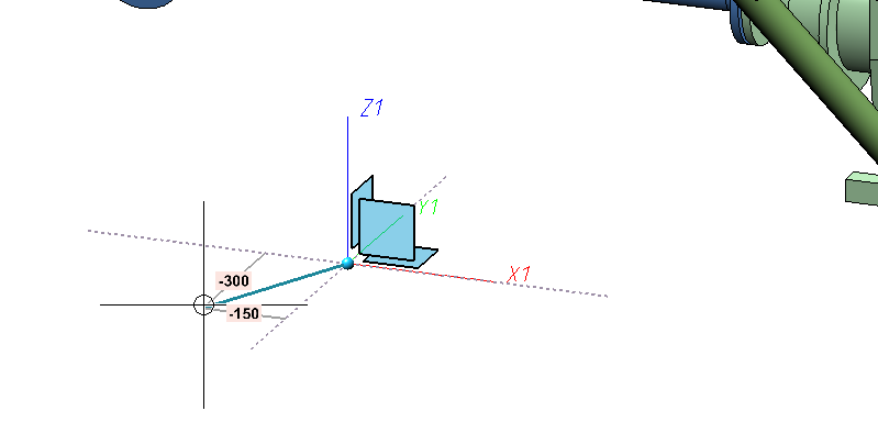
Therefore, unlike the 3-D Sketch function, when creating guideline sketches, the first point determined is also the origin of the sketch coordinate system..
When you call the Create guideline function, a coordinate system tripod is displayed at the cursor and its distance to the origin is additionally represented by auxiliary lines.
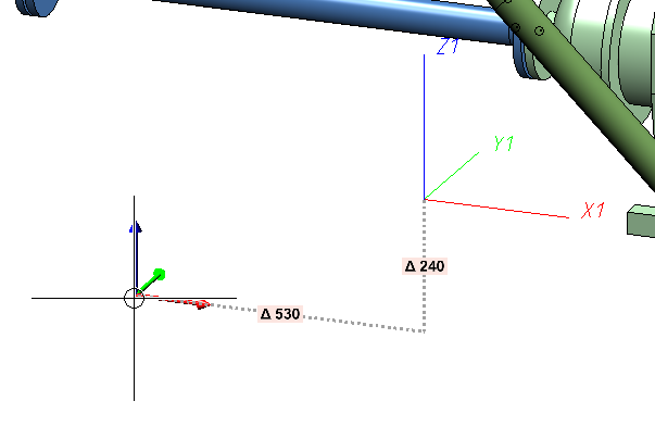
If you now select a point, the sketch coordinate system is the coordinate system previously indicated by the tripod at the cursor. Specifically, in the example above, the coordinate system tripod represents a moved version of the world coordinate system. Thus, the world coordinate system was used as the basis for the sketch coordinate system, with only its origin moved. This behaviour can be changed in the Configuration Editor.
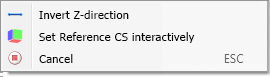
If you have selected the World CS or Local CS options in the Configuration Editor, the following context menu is available to you when selecting the first sketch point (see Settings in the Configuration Editor):
|
Invert Z-direction |
You can use this option to make the Z-axis of the sketch coordinate system point in the opposite direction. Especially at connecting points, the Z-axis can thus point into the connection instead of out. |
|
Set Reference CS interactively |
As with the regular sketch function, you will be prompted for the sketch coordinate system. So you always have the possibility to get full flexibility in choosing the coordinate system, if that should be necessary. |
|
Cancel |
Ends the function. |
After determining the first point, the usual drawing of the sketch begins. For this purpose, the Sketch polyline function is automatically started and with it the 3-D sketching tool. The sketching too, facilitates the construction by the fact that HiCAD - starting from the respective last point of a polyline - automatically displays auxiliary lines along a predefined grid and - depending on the selected mode - shows the corresponding angles, distances or radii at the cursor. On this grid you can, for example, determine the direction and length of a line with a mouse click by moving the cursor accordingly. Since 3-D sketches - like other 3-D parts - have a part coordinate system, the plane in which they are drawn can be changed at will during drawing. This drawing plane is always parallel to the selected plane and passes through the last determined point.
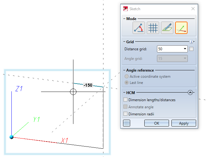
Extensive information about this can be found in the topic Sketching Tool for 3-D Sketches.
![]() Please note:
Please note:
- The guideline is created only when you actually draw lines.
- A selection of frequently used functions for editing guidelines can be found at

 . In addition, you can also use the functions from the Sketch Ribbon.
 - The former Guideline Editor is still available at Plant Engineering > Guideline > EndPt > Create guideline
 is still available.
Please note:
Unlike regular 3-D sketch-functions, the Create guideline and Sketch polyline functions of the Plant Engineering Ribbon will undo the entire change at once and not each added edge individually as in regular sketches.

Settings in the Configuration Editor
The behaviour regarding the sketch coordinate system of a guideline sketch can be defined in the Configuration Editor at Plant Engineering > C-edge via the Reference CS parameter.
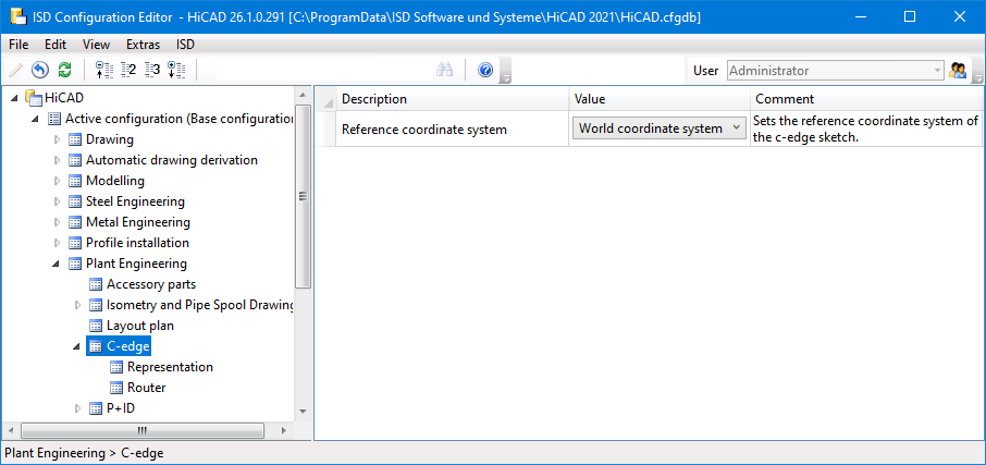
The following options are available:
- World CS
The sketch coordinate system of a guideline sketch is always set to the world coordinate system, moved to the first point of the sketch. This is the default setting.
- Local CS
The sketch coordinate system of a guideline sketch is always set to the local coordinate system, also moved to the first point of the sketch.
- Set interactively
As when creating a regular 3-D sketch, you are prompted to define a sketch coordinate system interactively. So this option disables the use of the first sketch point as the coordinate origin.
For the World CS and Local CS options, pipe part connecting points are handled in a special way. If you select such a point as the first point of the sketch, the sketch coordinate system is selected in such a way that its Z-axis points out of the connection belonging to the connecting point.
Tip:
If you select the option Local CS, you can use the Plant Engineering functions Set on connection and Set on guideline to easily set the origin of the sketch coordinate system relative to a pipe connection.

Guideline Tools (PE) • Create Guideline - Settings • Plant Engineering Functions